background image

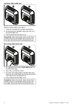
Inserting a MicroSD card

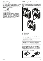
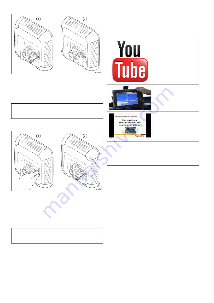
With the card reader’s cover open:
1. Insert the card with the contacts facing down.
2. Gently press the MicroSD card all the way into

the card reader slot.

3. Fully close the card reader cover.

Important:

When closing the cover ensure that it

is fully pushed in and sealed all the way around

the edge, this will provide the weatherproof seal.

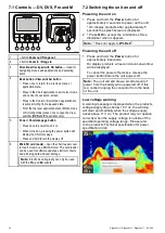
Removing a MicroSD card

1. On display products select

Eject SD Card

from

the Shortcuts page.

2. Open the card reader’s cover.
3. Pinch the protruding edge of the MicroSD card

between your index inger and thumb and pull the

card clear of the card reader slot.

4. Fully close the card reader cover.

Important:

When closing the cover ensure that it

is fully pushed in and sealed all the way around

the edge, this will provide the weatherproof seal.

7.11 Learning resources

Raymarine has produced a range of learning

resources to help you get the most out of your

products.

Video tutorials

Raymarine oficial channel on

YouTube:

http://www.youtube.com/u-

ser/RaymarineInc

Video Gallery:

http://www.rayma-

rine.co.uk/view/?id=2679

Product Support videos:

http://www.rayma-

rine.co.uk/view/?id=4952

Note:

• Viewing the videos requires a device with an

Internet connection.

• Some videos are only available in English.

Training courses

Raymarine regularly runs a range of in-depth training

courses to help you make the most of your products.

Visit the Training section of the Raymarine website

for more information:

http://www.raymarine.co.uk/view/?id=2372

FAQs and Knowledge Base

Raymarine has produced an extensive set of FAQs

and a Knowledge Base to help you ind more

information and troubleshoot any issues.

http://www.raymarine.co.uk/knowledgebase/

Technical support forum

You can use the Technical support forum to ask

a technical question about a Raymarine product

or to ind out how other customers are using

their Raymarine equipment. The resource is

regularly updated with contributions from Raymarine

customers and staff:

http://raymarine.ning.com/

58

Dragonly–4 / Dragonly–5 / Dragonly–7 / Wi–Fish

Summary of Contents for E70290

Page 1: ... 2016 Raymarine UK Limited 81358 3 Document number 01 2016 Date English EN INSTALLATION OPERATION INSTRUCTIONS DRAGONFLY ...

Page 2: ......

Page 3: ...SideVision Dragonly Quantum Instalert Infrared Everywhere and The World s Sixth Sense are registered or claimed trademarks of FLIR Systems Inc All other trademarks trade names or company names referenced herein are used for identiication only and are the property of their respective owners This product is protected by patents design patents patents pending or design patents pending Fair Use Statem...

Page 4: ......

Page 5: ...er 32 4 5 Finalizing the transducer mounting 33 Chapter 5 Cables and connections 35 5 1 General cabling guidance 36 5 2 Connections overview 36 5 3 Cable connection DV DVS Pro and Wi Fish 38 5 4 Connecting the power cable 5 M 38 5 5 Extension cable connection 41 Chapter 6 Wi Fish 43 6 1 Wi Fish controls 44 6 2 Switching the unit on and off 44 6 3 Wi Fish mobile app 45 6 4 Wi Fish initial set up 46...

Page 6: ...ance 110 12 2 Product cleaning 110 12 3 Transducer cleaning 111 Chapter 13 Troubleshooting 113 13 1 Troubleshooting 114 13 2 Power up troubleshooting 115 13 3 GPS troubleshooting 116 13 4 Sonar DownVision troubleshooting 117 13 5 Wi Fi troubleshooting 119 13 6 Miscellaneous troubleshooting 121 Chapter 14 Technical support 123 14 1 Raymarine product support and servicing 124 14 2 Learning resources...

Page 7: ...o a voltage supply greater than the speciied maximum rating may cause permanent damage to the unit Refer to the Technical speciication section for voltage rating Warning Product grounding Before applying power to this product ensure it has been correctly grounded in accordance with the instructions provided Warning Switch off power supply Ensure the vessel s power supply is switched OFF before sta...

Page 8: ...ne This product uses digital chart data and electronic information from the Global Positioning System GPS which may contain errors Raymarine does not warrant the accuracy of such information and you are advised that errors in such information may cause the product to malfunction Raymarine is not responsible for damages or injuries caused by your use or inability to use the product by the interacti...

Page 9: ...This device complies with Part 15 of the FCC Rules Operation is subject to the following two conditions 1 This device may not cause harmful interference 2 This device must accept any interference received including interference that may cause undesired operation FCC Interference Statement Part 15 105 b This equipment has been tested and found to comply with the limits for a Class B digital device ...

Page 10: ... units the screen may exhibit a few wrongly illuminated dead pixels These may appear as black pixels in a light area of the screen or as colored pixels in black areas If your display exhibits MORE than the number of wrongly illuminated pixels allowed refer to the product technical speciication for details please contact your local Raymarine service center for further advice Warranty policy Your pr...

Page 11: ...change speciications without notice As a result Raymarine cannot accept liability for any differences between the product and this document Please check the Raymarine website www raymarine com to ensure you have the most up to date version s of the documentation for your product Important information 11 ...

Page 12: ...12 Dragonly 4 Dragonly 5 Dragonly 7 Wi Fish ...

Page 13: ...and product information Chapter contents 2 1 Document information on page 14 2 2 Product overview on page 16 2 3 CHIRP DownVision overview on page 17 2 4 CHIRP Sonar overview on page 17 Document and product information 13 ...

Page 14: ... Chartplotter display with transducer E70290 Wi Fish Standalone single channel Wi Fi sonar module Note Dragonly products are standalone non networkable products Applicable chapters Some chapters in this manual are only applicable to certain product variants The table below shows which chapters are applicable to each product variant Chapter Variant Chapter 1 Important information All Chapter 2 Docu...

Page 15: ...llustrations in this document depending on product variant and date of manufacture All images are provided for illustration purposes only User manuals Print Shop Raymarine provides a Print Shop service enabling you to purchase a high quality professionally printed manual for your Raymarine product Printed manuals are ideal for keeping onboard your vessel as a useful source of reference whenever yo...

Page 16: ... with LightHouse charts Navionics and C Map charts by Jeppesen Dragonly 5 DVS 5 Bright all weather LED backlit display Dual channel CHIRP DownVision and CHIRP Sonar channels Supplied with CPT DVS Combined CHIRP DownVision CHIRP sonar and temperature transom mount transducer Easy ball and socket display mounting Dragonly 5 Pro 5 Bright all weather LED backlit display Dual channel CHIRP DownVision a...

Page 17: ... produces clear target returns The use of CHIRP processing and a higher operating frequency provide a more detailed image making it easier to identify bottom structures around which ish may reside CHIRP DownVision screen example 2 4 CHIRP Sonar overview CHIRP sonar produces a conical shaped beam the coverage of the conical beam is the water column directly beneath the vessel Conical beam Sonar is ...

Page 18: ...18 Dragonly 4 Dragonly 5 Dragonly 7 Wi Fish ...

Page 19: ...ducer compatibility on page 22 3 6 Tools required for installation Dragonly DV DVS Pro Wi Fish on page 23 3 7 Tools required for installation Dragonly 5 M on page 23 3 8 Software updates on page 24 3 9 Warnings and cautions on page 24 3 10 Selecting a location for the transducer on page 25 3 11 Cable routing on page 26 3 12 Selecting a location for the display on page 26 3 13 Installation process ...

Page 20: ... test the system 3 2 Parts supplied DV DVS and Pro variants The parts supplied with your product are shown below 1 Display unit 2 Locking collar 3 Pivot ball 4 M6 Hex bolt 5 Display bracket base 6 3 x M5 pozi drive bolt 7 3 x M5 washer 8 3 x M5 locking nut 9 Ratchet arm 10 Mounting bracket 11 M5 Hex ratchet bolt 12 Ratchet plate 13 Compression washer 14 M5 washer 15 M5 locking nut 16 3 x Self tapp...

Page 21: ...le 3 4 Parts supplied Wi Fish The parts supplied with your product are shown below 1 Wi Fish unit 2 Locking collar 3 Pivot ball 4 M6 Hex bolt 5 Unit bracket base 6 3 x M5 pozi drive bolt 7 3 x M5 washer 8 3 x M5 locking nut 9 Ratchet arm 10 Mounting bracket 11 M5 Hex ratchet bolt 12 Ratchet plate 13 Compression washer 14 M5 washer 15 M5 locking nut 16 3 x Self tapping screws 17 Documentation 18 Tr...

Page 22: ...acyDrago nly 7 DVS Pro Note Adaptor cable required for connection Note Connecting a CPT DV to a DVS or a Pro will prevent the Sonar application from functioning Connecting a CPT DVS to a DV or a or Wi Fish will not enable the Sonar application The M cannot be connected to a transducer Legacy and updated products Dragonly 6 Dragonly 7 displays and CPT 60 CPT 70 CPT 80 transducer designs have been m...

Page 23: ...ill also require marine grade sealant a waterproof fuse holder and 5 A inline fuse a paperclip in case you need to remove the transducer from the bracket 3 7 Tools required for installation Dragonly 5 M 1 Cordless drill 2 Pozi drive screw driver 3 8 mm wrench spanner 4 5 mm Hex wrench allen key 5 Drill bit You will also require a waterproof fuse holder and 5 A inline fuse Planning the installation...

Page 24: ...er or Raymarine technical support Caution Installing software updates The software update process is carried out at your own risk Before initiating the update process ensure you have backed up any important iles Ensure that the unit has a reliable power supply and that the update process is not interrupted Damage caused by incomplete updates are not covered by Raymarine warranty By downloading the...

Page 25: ...ropellers mount the transducer on the starboard side for counter clockwise mount on the port side On a twin engine vessel mount the transducer between the engines Turbulence can be caused by a number of other factors such as steps 1 ribs 2 rows of rivets 3 and strakes 4 The turbulence appears aft of these locations Air trapped under the front of the vessel can travel under the hull and appear as a...

Page 26: ...tion which allows proper routing and connection of cables Minimum cable bend radius of 100 mm 3 94 in is required unless otherwise stated Use cable supports to prevent stress on connectors Electrical interference Select a location that is far enough away from devices that may cause interference such as motors generators and radio transmitters receivers GPS location requirements In addition to gene...

Page 27: ...range of your Wi Fi product Maximum range will vary for each device Wi Fi performance degrades over distance so products farther away will receive less network bandwidth Products installed close to their maximum Wi Fi range may experience slow connection speeds signal drop outs or not being able to connect at all Line of sight and obstacles For best results the Wi Fi product should have a clear di...

Page 28: ...ugh room for display angle adjustment Allow enough head room to remove the display from the bracket Product dimensions Wi Fish Care points Allow of minimum of 120 mm 4 7 in behind the unit for inserting and removing an MicroSD card Allow enough room for unit angle adjustment Allow enough head room to remove the unit from the bracket 3 13 Installation process The steps listed below are required to ...

Page 29: ... 4 1 Mounting the transom mount bracket on page 30 4 2 Mounting the transducer on page 30 4 3 Mounting the unit on page 31 4 4 Testing and adjusting the transducer on page 32 4 5 Finalizing the transducer mounting on page 33 Mounting 29 ...

Page 30: ...ed on the transom using the mounting bracket provided The steps below describe the initial mounting steps required in order to test your transducers performance After testing the transducer you must inish the mounting following the instructions in the Finishing the transducer mounting section 1 Feed the transducer cable between the posts on the mounting bracket as shown 2 Slide the ratchet arm int...

Page 31: ...oles on the chosen mounting surface ii Drill holes for the ixings using a suitable drill ensuring there is nothing behind the surface that may be damaged iii Use a pozi drive screw driver and an 8 mm wrench spanner to attach the bracket base securely to the mounting surface using the ixings provided 4 Position the unit at the desired angle and secure by tightening the locking collar The unit can b...

Page 32: ...or or the bottom is missing at lower speeds then the transducer needs to be adjusted 6 Angle and height adjustments should be made in small increments and re tested each time until you obtain optimum performance 7 Loosen the ratchet arm bolt to adjust the transducer angle 8 Loosen the 2 mounting bracket screws to adjust the transducer height 9 Re tighten the ratchet arm bolt and mounting screws be...

Page 33: ...ounting bracket 2 Fill the locking hole with marine grade sealant 3 Secure the transducer and bracket by fully tightening all 3 mounting screws 4 Secure the ratchet arm bolt by tightening until the compression washer is compressed and then add another 1 4 turn If the transducer kicks up at speed then tighten further Important Take care to ensure that the pivot bolt is not overtightened as this wil...

Page 34: ...34 Dragonly 4 Dragonly 5 Dragonly 7 Wi Fish ...

Page 35: ...nts 5 1 General cabling guidance on page 36 5 2 Connections overview on page 36 5 3 Cable connection DV DVS Pro and Wi Fish on page 38 5 4 Connecting the power cable 5 M on page 38 5 5 Extension cable connection on page 41 Cables and connections 35 ...

Page 36: ...ways route data cables as far away as possible from other equipment and cables high current carrying AC and DC power lines antennae Strain relief Ensure adequate strain relief is provided Protect connectors from strain and ensure they will not pull out under extreme sea conditions Cable shielding Ensure that the cable is properly shielded that the cable shielding is intact e g hasn t been scraped ...

Page 37: ... Updated CPT 60 Updated CPT 70 Updated CPT 80 Legacy Dragonly 6 Legacy Dragonly 7 A80332 Legacy 1 keyway CPT 60 CPT 70 CPT 80 transducer toDragonly 4 Dragonly 5 and Wi Fish 3 keyway adaptor cable Legacy CPT 60 Legacy CPT 70 Legacy CPT 80 DV DVS Pro Wi Fish Updated Dragonly 6 Updated Dragonly 7 Legacy and updated products Dragonly 6 Dragonly 7 displays and CPT 60 CPT 70 CPT 80 transducer designs ha...

Page 38: ...the 12 V dc power supply 5 4 Connecting the power cable 5 M 1 Connect the power cable to the rear of the display and secure using the locking collar 2 The drain wire should be connected to the vessel RF ground point If your vessel has no ground point connect to the negative side of the vessel s power supply 3 The Negative wire must be connected to the negative side of the 12 V dc power supply 4 A ...

Page 39: ...It covers common vessel power arrangements but does NOT cover every scenario If you are unsure how to provide the correct level of protection please consult an authorized Raymarine dealer or a suitably qualiied professional marine electrician Implementation direct connection to battery The power cable supplied with your product may be connected directly to the vessel s battery via a suitably rated...

Page 40: ...eparate single length of 2 wire cable from the unit to the vessel s battery or distribution panel Raymarine recommends a minimum wire gauge of 18AWG 0 82 mm2 for any length of cable extension For all lengths of extension to the power cable ensure there is a continuous minimum voltage at the product s power connector of 10 8 V with a fully lat battery at 11 V Important Be aware that some products i...

Page 41: ...te Only 1 extension cable should be used per installation The length of the power supply wires on the extension cable is 2 m 6 6 ft Maximum transducer cable length The maximum cable length from the transducer to the unit is shown below CPT DV 8 m 26 2 ft 4 m 13 1 ft supplied cable 4 m 13 1 ft extension cable CPT DVS 10 m 32 8 ft 6 m 19 7 ft supplied cable 4 m 13 1 ft extension cable Note Extending...

Page 42: ...42 Dragonly 4 Dragonly 5 Dragonly 7 Wi Fish ...

Page 43: ...44 6 2 Switching the unit on and off on page 44 6 3 Wi Fish mobile app on page 45 6 4 Wi Fish initial set up on page 46 6 5 Depth Offset on page 46 6 6 Switching on the simulator Wi Fish app on page 47 6 7 Opening the MicroSD card reader cover on page 47 Wi Fish 43 ...

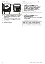
Page 44: ...s after approximately 5 seconds the splash screen is displayed 2 Press OK to accept the Limitations of Use disclaimer when it appears Note Does not apply to Wi Fish Powering the unit off 1 Press and hold the Power button for approximately 6 seconds On display products a 3 second count down timer will be displayed To cancel the power off process release the power button before the unit powers off N...

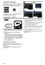
Page 45: ...hat you take note of these and retain somewhere safe for future reference 3 Open the Wi Fish app Connecting your smart device Your smart device s Wi Fi connection must be connected to the product to enable use of the mobile Wi Fish app With the Wi Fish mobile app installed on your smart device 1 Open the Wi Fi settings on your smart device and select your product s SSID from the list of available ...

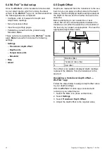
Page 46: ...so that the displayed depth reading represents the depth to the sea bed from either the keel or the waterline Before attempting to set a waterline or keel offset ind out the vertical separation between the transducer and either the waterline or the bottom of the keel on your vessel as appropriate Then set the appropriate depth offset value 1 Waterline offset 2 Transducer Zero offset 3 Keel offset ...

Page 47: ...r is located on the rear of the unit The card reader is protected by a weatherproof cover 1 Cover closed 2 Opening cover 3 Cover open 1 Open the card reader cover by pulling backwards on the cover s handle until the cover is positioned as shown in 3 above The cover has a tight it and may require some force to open the cover 2 Fully close the card reader cover Important When closing the cover ensur...

Page 48: ... this will provide the weatherproof seal Removing a MicroSD card 1 On display products select Eject SD Card from the Shortcuts page 2 Open the card reader s cover 3 Pinch the protruding edge of the MicroSD card between your index inger and thumb and pull the card clear of the card reader slot 4 Fully close the card reader cover Important When closing the cover ensure that it is fully pushed in and...

Page 49: ...p procedures on page 51 7 4 Satellite based navigation on page 52 7 5 Checking the sonar application on page 53 7 6 Checking the DownVision application on page 54 7 7 Shortcuts page on page 54 7 8 Applications on page 55 7 9 View switcher on page 56 7 10 Memory cards and chart cards on page 57 7 11 Learning resources on page 58 Getting started 49 ...

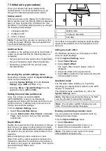
Page 50: ...only be used with the Pro and M variants 7 2 Switching the unit on and off Powering the unit on 1 Press and hold the Power button for approximately 3 seconds to power up the unit On display products after approximately 5 seconds the splash screen is displayed 2 Press OK to accept the Limitations of Use disclaimer when it appears Note Does not apply to Wi Fish Powering the unit off 1 Press and hold...

Page 51: ...r time and date preferences Depth Offset Depths are measured from the transducer to the sea bed but you can apply an offset value to the depth data so that the displayed depth reading represents the depth to the sea bed from either the keel or the waterline Before attempting to set a waterline or keel offset ind out the vertical separation between the transducer and either the waterline or the bot...

Page 52: ... signiies a greater positional error A typical receiver has an accuracy of between 5 and 15 m As an example assuming a receiver error of 5 m an HDOP of 2 would represent an error of approximately 15 m Please remember that even a very low HDOP igure is NO guarantee that your receiver is providing an accurate position If in doubt check the displayed vessel position in the Chart application against y...

Page 53: ...llite signal strength and other relevant information 7 5 Checking the sonar application Products which include the Sonar application and the CPT DVS transducer can use the Sonar application to help target ish From the Sonar application 1 Check the display With the transducer active you should see a scrolling left to right image that shows the bottom and underwater structure you should also see a d...

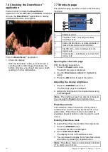
Page 54: ...ay powered on 1 Press the Power button once The shortcuts page is displayed 2 Use the Directional controls to highlight an option 3 Press the OK button to select the option Adjusting the display brightness 1 Press the POWER button once The Shortcuts page is displayed 2 Adjust the brightness to the required level using the Track pad Note The brightness level can also be increased by pressing the Po...

Page 55: ... If your display has a Back button you can also take a screenshot by pressing and holding the Back button until the conirmation message appears 7 8 Applications The applications available on your display are dependent upon product variant Description Applicable Products Chart application provides a 2D graphical view of your charts to help you navigate Waypoint and track functions enable you to nav...

Page 56: ... Back button Using the View switcher To select a view follow the steps below With the View switcher displayed 1 Use the Directional controls to highlight a view 2 Press the OK button to display the chosen view Selecting the active pane in splitscreen views When a splitscreen view is displayed you can change the active pane the pane that you want to control using the View switcher With a splitscree...

Page 57: ...hart card Raymarine recommends the use of quality branded memory cards Some brands of memory card may not work in your unit Please contact customer support for a list of recommended cards Removing MicroSD card from its adaptor MicroSD memory and cartography chart cards are usually supplied inserted into an SD card adaptor The card will need to be removed from the adaptor before inserting into your...

Page 58: ... your products Video tutorials Raymarine oficial channel on YouTube http www youtube com u ser RaymarineInc Video Gallery http www rayma rine co uk view id 2679 Product Support videos http www rayma rine co uk view id 4952 Note Viewing the videos requires a device with an Internet connection Some videos are only available in English Training courses Raymarine regularly runs a range of in depth tra...

Page 59: ...hinder applications features on page 62 8 4 Fishinder applications controls on page 62 8 5 Zoom on page 63 8 6 Range on page 64 8 7 Scrolling on page 64 8 8 A Scope mode on page 65 8 9 Display Options on page 65 8 10 Colors on page 66 8 11 Sensitivity adjustments on page 67 8 12 DV System settings menu options on page 68 Fishinder applications 59 ...

Page 60: ...he Sonar application uses CHIRP processing with a centered 200 KHz ping frequency which provides a greater depth range than DownVision but less detail The Sonar application displays a scrolling image which scrolls from right to left across the screen The Sonar application uses different colors to differentiate target strengths The colors used are dependent upon the selected color palette e g the c...

Page 61: ...the target to thicken and arch slightly at fast speeds the mark resembles a double vertical line Target depth The closer the target to the surface the larger the mark on screen The depth of individual targets can be displayed by switching on the Target Depth ID in the sonar menu Menu Display Options The number of target depths displayed is inluenced by the ish alarm sensitivity level Water depth A...

Page 62: ...g mode the controls behave as follows from the default view pressing the button enables Zoom mode when in Zoom mode use and buttons to increase or decrease the zoom level pressing the OK button opens the application menu pressing the Back button opens the View switcher not applicable to DV variants using any of the Directional controls will switch to Cursor Pause mode Cursor Pause mode Important T...

Page 63: ... the context menu by following the steps below 1 Use the Directional controls to highlight an object or area 2 Press the OK button The context menu is displayed 8 5 Zoom The Zoom function displays more detail onscreen by magnifying a speciic area of the image When using Zoom the screen is split and displays the zoomed image alongside the standard image Sonar application DownVision application This...

Page 64: ...th to be displayed onscreen follow the steps below From the application menu 1 Select Range 2 Select Range so that Man is selected 3 Select Shallow Range The Shallow Range deines the depth that will be shown at the top of the screen 4 Adjust the Shallow Range to the required depth 5 Select Deep Range The Deep Range deines the depth that will be shown at the bottom of the screen 6 Adjust the Deep R...

Page 65: ...h features and manipulate the image to enable easier ish targeting Available depth features Target Depth ID Not available in DownVision application Depth Lines White Line Not available in DownVision application Enabling Disabling Target Depth ID You can display the depth of targets on screen From the application menu 1 Select Display Options 2 Select Target Depth ID Selecting Target Depth ID will ...

Page 66: ...s Classic Blue default Classic Black Classic White Sunburst Night Vision DownVision application color palettes Copper Inv Copper Slate Gray Inv Slate Gray Selecting colors The Colors used can be changed at any time by selecting an option from the relevant menu Menu Display Options Color Palette DV variants Menu Display Options Sonar Colors DVS and Pro variants Menu Display Options DownVision Color...

Page 67: ...cation however for optimum performance in most conditions it is recommended that you use the auto setting All echoes with a signal strength above the speciied value are displayed in the strongest color shade Those with a weaker value are divided equally between the remaining colors shades Setting a low value produces a wide band for the weakest color shade but a small signal band for the other col...

Page 68: ...tivity or DownVision Sensitivity 2 Select Noise Filter 3 Use the Up and Down Directional controls to adjust the Noise Filter to the required value or 4 Press the OK button to switch between Auto and Manual 8 12 DV System settings menu options The System Settings menu on the DV variant display is located in the main application menu Refer to 11 1 System Settings menu for details on available option...

Page 69: ...page 84 9 8 Navigation on page 84 9 9 Chart settings menu cartography compatibility on page 85 9 10 Chart selection on page 86 9 11 Chart Detail on page 86 9 12 High resolution bathymetry on page 87 9 13 Chart orientation on page 87 9 14 Text and Symbol size on page 88 9 15 Boat position on page 89 9 16 Community layer on page 89 9 17 Sonar logging on page 90 9 18 COG Vector on page 90 9 19 Deep W...

Page 70: ...earing and distance to the cursor s location from your vessel is displayed 11 Waypoint TTG Applies to Dragonly 7 only During active navigation the estimated time to go to the target cursor waypoint based on your current speed is displayed 12 Cursor Used to select chart objects and move around the chart area 13 Target waypoint Current target waypoint 14 Vessel coordinates Applies to Dragonly 7 only...

Page 71: ...ding LightHouse Charts to MicroSD card using the LightHouse Download Manager Raster charts Raster charts are an exact copy scan of an existing paper chart All information is embedded directly in the chart Ranging in and out of raster charts will make everything appear larger or smaller on the screen including text When changing the Chart application s orientation everything on the chart will rotat...

Page 72: ...o the card reader of your multifunction display 8 Open the Chart application on your multifunction display 9 Select the new chart from the Chart selection menu Menu Presentation Chart Selection The Chart screen will be redrawn to display the newly selected chart type Navionics charts Your display is supplied with a base map and depending on unit a Navionics chart card You may also purchase Navioni...

Page 73: ...t symbol remains centered onscreen and the Chart area moves around the boat symbol In Motion mode the controls behave as follows pressing the button ranges in pressing the button ranges out pressing the Ok button opens the Chart application menu pressing the Back button opens the View switcher pressing any of the Directional controls enters Cursor mode Cursor mode In Cursor mode the Directional co...

Page 74: ...cts 9 4 Waypoints overview Waypoints are position markers used for the purposes of navigation Your display can create waypoints which can then be selected for active navigation There are a range of features for placing navigating and managing waypoints these can be accessed from the Waypoints menu and Waypoint context menu Waypoints are represented onscreen using customizable waypoint symbols Wayp...

Page 75: ...desired location with the cursor 2 Press the OK button The context menu is displayed 3 Select Place Waypoint A conirmation pop up message is displayed 4 Select Ok to place the waypoint or Edit to edit the waypoint details A waypoint is placed at the cursor s location Placing a waypoint at your vessel s position From the Chart application 1 If required press the Back button to enter motion mode 2 P...

Page 76: ...int group With the Waypoint Group List displayed 1 Select New Group The on screen keyboard is displayed 2 Use the on screen keyboard to enter the required name for the new group 3 select SAVE Renaming a waypoint group With the Waypoint group list displayed 1 Select the group you want to rename Group details are displayed 2 Select Rename Group The on screen keyboard is displayed 3 Using the on scre...

Page 77: ...that has been created and stored The following information is assigned or captured for each waypoint Symbol a default symbol is assigned or you can select an alternative Name a default name is assigned or you can select an alternative Position Latitude and Longitude of the waypoint Bearing and Range Bearing and range from vessel Temperature requires appropriate sensor only for waypoints captured a...

Page 78: ...ta that you want to keep on to a MicroSD card From the Backup Reset menu 1 Select Erase from System 2 Select Erase Waypoints from System A conirmation dialog is displayed 3 Select Yes to conirm Accessing the backup reset menu Depending on display variant the Backup Reset menu can be accessed by selecting Backup Reset from the Tools Settings page Pro variants or by selecting Menu System settings Ba...

Page 79: ...points list is displayed 2 Select Search The search page is displayed 3 Select Area The Chart application is displayed with the area search menu open 4 Select the location for the irst corner point of the search area 5 Select the location for the opposite corner of the search area A box is drawn on the screen which covers the selected area If the box is drawn in the wrong place you can draw a new ...

Page 80: ...lockwise Marker Restriction Bottom Mark Top Mark Route Start Route End Diver Down Diver Down 2 Oil Rig Filled Circle FAD Fish Attracting Device Concrete Rubble Seaweed Oyster Green Can Green Nun Red Can Red Nun Yellow Can Yellow Nun Fish Trap Brushpile Preferred Marks Post Ledge Fish Fish 1 Star Fish 2 Star Fish 3 Star School Fish Lobster Small Fish Rocks Reef Private Reef Public Reef Dolphin Shar...

Page 81: ... a break will occur in the track Note If the maximum number of tracking points is reached you will be warned The track will continue to be recorded with the earlier tracking points being overwritten 4 To complete your track select Stop Track from the Navigate menu Menu Navigate Stop Track The track stopped pop up message is displayed 5 Select Save Erase or Cancel Save Will save the track and open ...

Page 82: ...creen keyboard is displayed 3 Use the on screen keyboard to change the track name 4 When inished Select SAVE You can also edit track details by selecting Edit Track from the track context menu Changing the color of a track You can change the color of a saved track With the track list displayed 1 Select the track you want to edit The track options page is displayed 2 Select Edit Color A list of col...

Page 83: ...ng waypoints or tracks from a memory card Chartplotter variant displays can import waypoints and tracks from MicroSD card Ensure that the MicroSD card that contains your saved waypoints and or tracks is inserted into the card reader From the Chart application 1 If required press the Back button to enter Motion mode 2 Press the OK button to display the menu 3 Select Waypoints or Tracks as required ...

Page 84: ...k button to enter motion mode 2 Press the OK button to open the menu 3 Select Waypoints The Waypoints list is displayed 4 Select the waypoint you want to navigate to The Waypoint information page is displayed 5 Select Goto Cancelling navigation to a waypoint 1 Select any position anywhere on screen The waypoint context menu is displayed 2 Select Stop Goto 3 Alternatively in the chart application g...

Page 85: ...e is not compatible then the menu option will not be shown Menu option Compatible cartography Chart Selection LightHouse Charts Navionics Charts Jeppesen Chart Detail LightHouse Charts Navionics Charts Jeppesen High Res Bathy Jeppesen Chart Orientation LightHouse Charts Navionics Charts Jeppesen Text Symbol Size Jeppesen Boat Position Navionics Charts Community Edits LightHouse Charts Navionics Ch...

Page 86: ...3 Select the cartography type you want to display The Chart window is re drawn to show the select cartography type 9 11 Chart Detail The chart detail setting determines the amount of detail shown in the Chart application Selecting the Low option for the Chart Detail disables the following objects Community Layer Chart Text Chart Boundaries Light Sectors Routing Systems Caution Areas Marine Feature...

Page 87: ...p between the chart and the direction that you are travelling in The mode you choose applies to all chart views and is restored at power up The following options are available North Up In North Up mode the Chart Orientation is ixed with true north pointing up this is the usual orientation for nautical charts As your heading changes the vessel symbol rotates accordingly This is the default orientat...

Page 88: ...to Large Normal Large Switching text and symbol size If supported by your cartography type the display text and symbols size can be increased From the Chart application menu 1 Select Chart Setting 2 Select Text Symbol Size so that Large is selected to increase the size of text and symbols in the Chart application or 3 Select Text Symbol Size so that Normal is selected to reduce text and symbol siz...

Page 89: ...ion between Center and Offset 9 16 Community layer If supported by your cartography type you can display User Generated Content UGC on the Chart application 1 Community feature On 2 Community feature Off To check if your Navionics cartography supports community edits downloads please refer the Navionics website for information and instructions on downloading the updates to your chart card Switchin...

Page 90: ...bling Sonar logs Sonar logging can be enabled or disabled at any time From the Chart application menu 1 Select Chart Setting 2 Select Sonar Logs so that On is selected to enable sonar logging or 3 Select Sonar Logs so that Off is selected to disable sonar logging 9 18 COG Vector The chart application can be set to display a green line to represent Course Over Ground COG The green line indicates th...

Page 91: ...uld see in a marine almanac Pilot book information is available at certain ports Panoramic photos of ports and marinas The availability of photos is indicated by a camera symbol on the chart display This information can be accessed using the chart context menu options Note The amount of object information available depends upon the electronic charts that you are using for your system For full deta...

Page 92: ...u The System Settings menu on the 5 M variant display is located in the main application menu Refer to 11 1 System Settings menu for details on available options for your display variant 92 Dragonly 4 Dragonly 5 Dragonly 7 Wi Fish ...

Page 93: ...Chapter 10 Mobile applications Chapter contents 10 1 Wi Fish mobile app on page 94 10 2 Connecting Wi Fi Pro displays on page 94 Mobile applications 93 ...

Page 94: ...anged if desired Tools Settings WiFi Settings 3 Open the Wi Fish app Connecting your smart device Your smart device s Wi Fi connection must be connected to the product to enable use of the mobile Wi Fish app With the Wi Fish mobile app installed on your smart device 1 Open the Wi Fi settings on your smart device and select your product s SSID from the list of available devices Your product s SSID ...

Page 95: ...Chapter 11 Tools Settings Chapter contents 11 1 System Settings menu on page 96 11 2 Alarms on page 102 11 3 Backup and reset on page 105 11 4 Wi Fi Settings on page 107 Tools Settings 95 ...

Page 96: ...d Units Depth Units Temperature Units GPS Set up Pro 5 M Provides GPS setting options View Satellite Status COG SOG Filter Restart GPS Note Only available on displays with an internal GPS GNSS receiver Sonar Set up DV DVS Pro Provides sonar setting options Depth Offset W Sonar Reset Waypoint Arrival Alarm 5 M When you arrive at a waypoint an alarm is triggered This setting allows you to specify th...

Page 97: ... the DV variant display is located in the main application menu Refer to 11 1 System Settings menu for details on available options for your display variant 5 M System settings menu The System Settings menu on the 5 M variant display is located in the main application menu Refer to 11 1 System Settings menu for details on available options for your display variant System Languages The system can o...

Page 98: ...application You can set up your receiver and check its status from the GPS Set up menu For each satellite the screen provides the following information 1 Sky view 2 Satellite status 3 Position and ix information Sky view Sky view is a visual representation that shows the position of navigation satellites and their type Satellite types are Circle A circle identiies a satellite from the GPS constell...

Page 99: ...the Chart application In order for your receiver and MFD to correlate accurately with your paper charts they must be using the same datum COG SOG Filter The COG SOG ilter averages the velocity vectors to compensate for the oscillating motion of the vessel giving a clearer indication of the vessel s course and speed The ilter does not affect the calculation of your receiver s reported position The ...

Page 100: ... hour increments 13 to 13 hours in 0 5 hour increments Simulator mode The Simulator mode enables you to practice operating your display without data from the GPS receiver or transducer The simulator mode is switched on off in the System Settings menu Note Raymarine recommends that you do NOT use the simulator mode whilst navigating Note The simulator will NOT display any real data This includes sa...

Page 101: ... affect your waypoints or tracks Yes No Settings and Data Reset In addition to the settings reset detailed above performing a settings and data reset will also remove ALL waypoint and track data Yes No Back up Settings Back up settings to a memory card Restore Settings Restore saved settings from a memory card Save Logs Allows you to save error logs to SD card for troubleshooting purposes Erase Lo...

Page 102: ...from the Alarms menu Accessing the alarms menu Depending on display variant the Alarms menu can be accessed by selecting Tools Settings from the View Switcher Dragonly 4 Pro Dragonly 5 Pro and Dragonly 7 or by selecting System Settings from the application menu Dragonly 4 DV Dragonly 4 DVS Dragonly 5 DVS and Dragonly 5 M 102 Dragonly 4 Dragonly 5 Dragonly 7 Wi Fish ...

Page 103: ...ered if any target meets the sensitivity level and is within the Shallow Fish Limit and Deep Fish Limit that you specify The following items are available in the sub menu Fish Switches ish alarm On and Off Fish Sensitivity If the Fish alarm is set to On an alarm is triggered when the ish return strength reaches the sensitivity that you specify Fish Depth Limits Switches depth limits On and Off Sha...

Page 104: ...degrees fahrenheit or equivalent units Waypoint Arrival Alarm Pro When you arrive at a waypoint an alarm is triggered This setting allows you to specify the distance from the target waypoint at which the alarm is triggered 0 01 to 9 99 nm or equivalent units 104 Dragonly 4 Dragonly 5 Dragonly 7 Wi Fish ...

Page 105: ...ommended that you save user data and settings to a separate memory card and NOT to a chart card containing cartography Erasing all waypoints from the system Note The following procedure permanently deletes all Waypoints from the display BEFORE proceeding ensure that you backup any data that you want to keep on to a MicroSD card From the Backup Reset menu 1 Select Erase from System 2 Select Erase W...

Page 106: ...Tools Settings page 1 Select Backup Reset 2 Select User Settings 3 Select Settings Reset A message is displayed prompting you to conirm the action 4 Select Yes to proceed with the settings reset or No to cancel If Yes is selected the system will reboot and the settings will be reset to factory defaults Resetting system settings and data Note Performing a settings and data reset erases ALL waypoint...

Page 107: ...can be changed to a more memorable password Onscreen keyboard is displayed Wi Fi Channel You can change the Wi Fi channel to as less congested channel Changing the Wi Fi channel can help to resolve intermittent Wi Fi connection issues 1 to 11 Wi Fi Security By default the recommended security type WPA2 Only is enabled There should be no need to change the security type however if your device does ...

Page 108: ...108 Dragonly 4 Dragonly 5 Dragonly 7 Wi Fish ...

Page 109: ...Chapter 12 Maintenance Chapter contents 12 1 Service and maintenance on page 110 12 2 Product cleaning on page 110 12 3 Transducer cleaning on page 111 Maintenance 109 ...

Page 110: ...lay unit is a sealed unit and does not require regular cleaning If it is necessary to clean the unit follow this basic procedure 1 Switch off the power to the display 2 Wipe the display with a clean soft cloth a microibre cloth is ideal 3 If necessary use a mild detergent to remove grease marks Note Do NOT use solvents or detergents on the screen itself Note In certain conditions condensation may ...

Page 111: ...temperature sensor may not work properly if painted Note Never use ketone based paint Ketones can attack many plastics possibly damaging the sensor Note Never use spray paint on your transducer Spraying incorporates tiny air bubbles and a marine transducer cannot transmit properly through air Use a soft cloth and mild household detergent to clean the transducer If the fouling is severe remove the ...

Page 112: ...112 Dragonly 4 Dragonly 5 Dragonly 7 Wi Fish ...

Page 113: ...eshooting on page 114 13 2 Power up troubleshooting on page 115 13 3 GPS troubleshooting on page 116 13 4 Sonar DownVision troubleshooting on page 117 13 5 Wi Fi troubleshooting on page 119 13 6 Miscellaneous troubleshooting on page 121 Troubleshooting 113 ...

Page 114: ... shipping subjected to comprehensive test and quality assurance programs However if you experience problems with the operation of your product this section will help you to diagnose and correct problems in order to restore normal operation If after referring to this section you are still having problems with your unit please contact Raymarine Technical Support for further advice 114 Dragonly 4 Dra...

Page 115: ...onnections for cable and connection requirements Power source insuficient With the product under load using a multi meter check the power supply voltage as close to the unit as possible to establish actual voltage when the current is lowing Refer to Chapter 15 Technical speciication for power supply requirements Product will not boot up re boot loop Possible causes Possible solutions Power supply ...

Page 116: ...ion A GPS Status page is available This provides satellite signal strength and other relevant information Location of product For optimum performance the unit should be mounted above decks and not be in close proximity to any structural bulkheads or other electrical equipment or cables which may cause interference Refer to Chapter 3 Planning the installation for details on product location require...

Page 117: ...y ensure you are using a dual element transducer such as the CPT DVS Refer to 3 5 DownVision transducer compatibility for transducer compatibility No depth reading lost bottom lock Possible causes Possible solutions Transducer location Check that the transducer has been installed in accordance with the transducer location requirements refer to 3 10 Selecting a location for the transducer of the ma...

Page 118: ...his causes the unit to re boot loose power replace if necessary 5 Check the vessel s battery voltage the condition of the battery terminals and power supply cables ensuring connections are secure clean and free from corrosion replace if necessary 6 With the product under load using a multi meter check for high voltage drop across all connectors fuses etc this can cause the Fishinder applications t...

Page 119: ...ssphrase the Wi Fi network s passphrase can be found in the Wi Fi settings on the broadcasting device the device that you are trying to connect to Possible cause Possible solutions Bulkheads decks and other heavy structure can degrade and even block the Wi Fi signal Depending on the thickness and material used it may not always be possible to pass a Wi Fi signal through certain structures 1 Try re...

Page 120: ...on other vessels When in close proximity to other vessels for example when moored up in a marina many other Wi Fi signals may be present 1 Change the Wi Fi Channel of the device you are trying to connect to and retry the connection You can use free Wi Fi analyzer apps on your smart device to help you choose a better channel channel with least trafic 2 If possible move your vessel to a location wit...

Page 121: ...ck that the power source is of the correct voltage and suficient current Ensure you have the latest software Check the Raymarine website regularly for software updates for your product www raymarine com Display behaves erratically Frequent unexpected resets System crashes or other erratic behavior Corrupt data other unknown issue Perform a Settings and Data Reset Important This will result in the ...

Page 122: ...122 Dragonly 4 Dragonly 5 Dragonly 7 Wi Fish ...

Page 123: ...Chapter 14 Technical support Chapter contents 14 1 Raymarine product support and servicing on page 124 14 2 Learning resources on page 125 Technical support 123 ...

Page 124: ...25 FAQ Knowledgebase http www rayma rine co uk knowledgebase Technical support forum http rayma rine ning com Software updates http www rayma rine com software Telephone and e mail support Region Tele phone E mail United Kingdom UK EMEA and Asia Paciic 44 0 1329 246 777 support uk raymarine com United States US 1 603 324 7900 Toll free 800 539 5539 support raymarine com Region Tele phone E mail Au...

Page 125: ...f in depth training courses to help you make the most of your products Visit the Training section of the Raymarine website for more information http www raymarine co uk view id 2372 FAQs and Knowledge Base Raymarine has produced an extensive set of FAQs and a Knowledge Base to help you ind more information and troubleshoot any issues http www raymarine co uk knowledgebase Technical support forum Y...

Page 126: ...126 Dragonly 4 Dragonly 5 Dragonly 7 Wi Fish ...

Page 127: ...eciication Dragonly 4 on page 128 15 2 Technical speciication Dragonly 5 on page 129 15 3 Technical speciication Dragonly 7 on page 130 15 4 Technical speciication Wi Fish on page 131 15 5 Technical speciication CPT DV and CPT DVS on page 131 Technical speciication 127 ...

Page 128: ...ty Maximum 75 Waterproof rating IPX6 and IPX7 Sonar DownVision speciication The following speciication only applies to DownVision products Channels 2 x CHIRP 1 x traditional sonar and 1 x DownVision Beam coverage Sonar conical beam DownVision Wide port starboard and thin fore aft fan beam Depth range 0 6 M 2 ft to 183 m 600 ft Depending on water conditions the Sonar channel maybe able to achieve i...

Page 129: ...humidity Maximum 75 Waterproof rating IPX6 and IPX7 Sonar DownVision speciication The following speciication only applies to DownVision products Channels 2 x CHIRP 1 x traditional sonar and 1 x DownVision Beam coverage Sonar conical beam DownVision Wide port starboard and thin fore aft fan beam Depth range 0 6 M 2 ft to 183 m 600 ft Depending on water conditions the Sonar channel maybe able to ach...

Page 130: ... 158 ºF Relative humidity Maximum 75 Waterproof rating IPX6 and IPX7 Sonar DownVision speciication Channels DV DVS Pro Wi Fish 1 x DownVision channel DVS Pro 1 x CHIRP sonar channel Beam coverage CHIRP Sonar conical beam DownVision Wide port starboard and thin fore aft fan beam Depth range 0 6 M 2 ft to 183 m 600 ft Depending on water conditions the Sonar channel maybe able to achieve increased de...

Page 131: ...midity Maximum 75 Waterproof rating IPX6 and IPX7 Sonar DownVision speciication The following speciication only applies to DownVision products Channels 2 x CHIRP 1 x traditional sonar and 1 x DownVision Beam coverage Sonar conical beam DownVision Wide port starboard and thin fore aft fan beam Depth range 0 6 M 2 ft to 183 m 600 ft Depending on water conditions the Sonar channel maybe able to achie...

Page 132: ...132 Dragonly 4 Dragonly 5 Dragonly 7 Wi Fish ...

Page 133: ...Chapter 16 Spares and accessories Chapter contents 16 1 Spares Accessories on page 134 Spares and accessories 133 ...

Page 134: ...transducer power extension cable A80312 CPT DV CPT DVS 3 keyway to Legacy Dragonly 6 Dragonly 7 1 keyway adaptor cable A80331 Legacy 1 keyway CPT 60 CPT 70 CPT 80 transducer toDragonly 4 Dragonly 5 and Wi Fish 3 keyway adaptor cable A80332 Spares Description Part numbers Display mounting bracket R70375 CPT DV CPT DVS transom mount bracket R70439 Dragonly 5 M 1 5 m 4 9 ft power cable R70376 CPT DV ...

Page 135: ......

Page 136: ...www raymarine com Raymarine UK Limited Marine House Cartwright Drive Fareham PO15 5RJ United Kingdom Tel 44 0 1329 246 700 ...
Reviews: