Flavor Burst FB 80S-08 Manual Download Page 63


62

2.  Touch the #1 key on the keypad and 
read the SYRUP OUTPUT level bar 
graph.  Write down the level value 1-0 
as your first number on the right.   10 on 
the bar graph represents 0.   (See 
Figure 160.)   


Figure 160


3.  Touch the #2 key on the keypad and 
read your SYRUP OUTPUT bar graph.  
Write down the value as your second 
number from the right.   (See  
Figure 161.)   


Figure 161


4.  Touch the #3 key and record as your 
third number from the right.     (See 
Figure 162.)   


Figure 162


5.  Touch the #4 key and record as your 
fourth number from the right.   (See 
Figure 163.)   


Figure 163


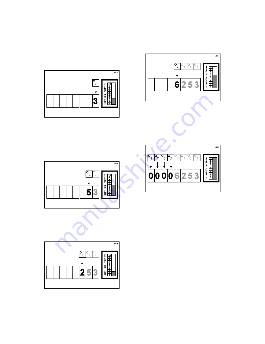
6.  Repeat with selections #5- #8 
recording each number down from the 
right to left.  Remember that 10 on the 
bar graph represents 0.   (See  
Figure 164.)   


Figure 164


7.  The final number (in this example 
6,253) is your total serving count.  
Deduct the previous day’s reading from 
the current reading to determine the 
current day’s serving count. 
 

8.  

To exit the ACCESS COUNT 

READOUT mode, press the OFF         
key.


Summary of Contents for FB 80S-08

Page 1: ... concerns regarding the warranty should be clarified upon delivery or installation For more information contact your local authorized Flavor Burst distributor 2006 Flavor Burst Company Reprinted in September Printed in All Rights Reserved The United States of America Introduction 1 Safety Precautions 1 Parts Identification Function 3 Daily Opening Procedures 18 Daily Closing Procedures 22 Replacin...

Page 2: ...ment cabinet in 1 gallon disposable bags Proper syrup injection rate is maintained by adjusting the flavor level on the system keypad Components of the FB 80S system should be cleaned daily to ensure the highest standard of sanitation When your equipment is delivered or if it has been unused for more than 24 hours follow the DAILY OPENING PROCEDURES SAFETY PRECAUTIONS Always follow these safety pr...

Page 3: ...nstructions may result in serious electrical shock NOISE LEVEL Airborne noise emission does not exceed 70 dB A when measured at a distance of 1 0 meter from the surface of the machine and at a height of 1 6 meters from the floor NOTE Operations Manual subject to change Contact your local distributor for most recent updates concerning the FB 80S unit ...

Page 4: ...3 PARTS IDENTIFICATION FUNCTIONS General System Overview See Figure 1 ...

Page 5: ...4 Figure 1 ...

Page 6: ...5 Cabinet See Figure 2 ...

Page 7: ...6 Figure 2 ...

Page 8: ...7 Blending Assembly and Related Parts See Figure 3 ...

Page 9: ...8 Figure 3 ...

Page 10: ...9 Syrup Pump and Related Parts See Figure 4 ...

Page 11: ...10 Figure 4 ...

Page 12: ...11 Sanitizer Pump and Related Parts See Figure 5 ...

Page 13: ...12 Figure 5 ...

Page 14: ...13 Electronic Parts and Connections See Figure 6 ...

Page 15: ...14 Figure 6 ...

Page 16: ...15 Spare Parts Kit See Figure 7 ...

Page 17: ...16 Figure 7 ...

Page 18: ...17 ...

Page 19: ... REPLACE IF NECESSARY Ensure that the Blending System has been disassembled and cleaned according to the DAILY CLOSING PROCEDURES This is typically performed at the close of the previous business day Sanitizing the Blending System 1 Prepare approved sanitizer solution according to manufacturer s instructions 2 Remove the Manifold cap and set it on a sanitary tray Spray the 9 Tube Assembly Manifold...

Page 20: ... Bracket to dry See Figure 11 Figure 11 6 The following do not need to be sanitized on a daily basis as part of the daily opening procedures However inspect these areas and if necessary clean according to instructions in the SCHEDULED MAINTENANCE section See Figure 12 9 Tube Assembly Coupler 9 Tube Assembly Tubes Spigot Switch Keypad and Keypad Bracket Blending Adapter clean according to instructi...

Page 21: ...re See Figure 13 Figure 13 2 Open the Mounting Bracket and install it over the Blending Assembly and onto the door post See Figure 14 Figure 14 3 Close the bracket over the door post and behind the Blending Assembly See Figure 15 Figure 15 4 Insert the 9 Tube Assembly manifold fully into the Blending Head syrup line opening Rotate it until motion stops to secure See Figure 16 Figure 16 5 With a co...

Page 22: ... adjusted if necessary 1 Ensure that the Sanitizer Tank has plenty of approved sanitizer solution and refill according to instructions if necessary 2 Ensure that desired flavors are installed and that none of the flavor bags are empty Replace flavors according to instructions if necessary 3 Ensure that the flavor level and the multi flavored timing are set to a desired level Make adjustments accor...

Page 23: ...ending System Follow these instructions to remove the Blending System from the freezer during closing 1 With a container under the dispensing spout press the ROTOR FLUSH key on the Keypad to purge any remaining product from the Blending Head See Figure 18 Figure 18 2 Rotate the 9 Tube Assembly coupler until it unlocks and is able to slide out of the Blending Head syrup line opening See Figure 19 F...

Page 24: ... Tube Assembly Manifold opening with approved sanitizer solution and allow it to sanitize for at least 1 minute See Figure 23 Figure 23 3 Place the 9 Tube Assembly in a container to catch the sanitizer solution during the Rotor Flush function See Figure 24 Figure 24 4 With the Blending Head tilted downward brush and clean all exposed surfaces of the Blending Head with detergent water and then rins...

Page 25: ...nitizer solution keeping the Drive Motor above the water line Press ROTOR FLUSH to sanitize the enclosed auger Allow the Blending Head to soak for at least 1 minute See Figure 27 Figure 27 7 Place the cap on the 9 Tube Assembly and hang it with Blending Assembly the Accessory Hanging Bracket to dry See Figure 28 Figure 28 8 Clean rinse and dry the surfaces of the Blending Motor the Keypad and expo...

Page 26: ...ding to instructions in the SCHEDULED MAINTENANCE section See Figure 30 9 Tube Assembly Coupler 9 Tube Assembly Tubes Spigot Switch Keypad Bracket Blending Adapter clean according to instructions when freezer door has been removed Outer surfaces of Blending Motor Areas inside and under Cabinet Mounting Bracket Figure 30 ...

Page 27: ...vious flavors become empty However you may change flavors periodically as desired 1 Mix approved detergent with warm water according to manufacturer s instructions Also prepare approved sanitizer solution according to manufacturer s instructions 2 Complete Phase 2 of the Clean In Place procedure except Step 17 to sanitize the syrup line NOTE BE SURE TO PLACE A CONTAINER UNDER THE BLENDING HEAD TO ...

Page 28: ... is set back down allow the bag to settle in the tray See Figure 36 Figure 36 9 Make sure the syrup bag is settled neatly into the tray and then install the loaded tray into the cabinet See Figure 37 Figure 37 10 Clean the exposed surfaces of the Syrup Bag Connector and bag fitment with detergent water and a single service towel and brush if necessary Then rinse and dry the connector and fitment u...

Page 29: ...product to be dispensed and press PUMP FLUSH to prime the syrup line See Figure 41 Figure 41 15 Once syrup flows consistently from the Blending Head press OFF to complete the procedure NOTE THE PUMP FLUSH FUNCTION WILL AUTOMATICALLY SHUT OFF AFTER 5 MINUTES NOTE YOU MAY WANT TO PROCEED WITH STEP 16 AS TIME ALLOWS DURING THE PUMP FLUSH FUNCTION IF AN ADDITIONAL FLAVOR NEEDS TO BE INSTALLED 16 Repea...

Page 30: ...29 ...

Page 31: ...lization The medium used for this process must be an approved sanitizing product mixed according to the product manufacturer s instructions This Clean In Place procedure is detailed in 3 phases 1 9 Tube Assembly Cleaning 2 Syrup System Cleaning and 3 Reassembly To ensure maximum results the following instructions should be completed in sequence as stated This will expose the system and parts to th...

Page 32: ...brushing through each valve opening Rinse thoroughly See Figure 47 Figure 47 7 Place the items in the approved sanitizer solution Allow these items to soak throughout the upcoming processes See Figure 48 Figure 48 Phase 2 Syrup System Cleaning NOTE THE FOLLOWING CLEAN IN PLACE PROCEDURE STEPS 8 17 SHOULD BE COMPLETED CONSECUTIVELY BEGINNING WITH SYRUP LINE 1 I E 1 2 3 4 5 6 7 8 UNTIL ALL 8 SYRUP L...

Page 33: ...aling the inner casing and insert the Pump Flush Adapter into the Connector Release the Connector Head to secure the connection See Figure 52 Figure 52 13 Touch the number on the Keypad 1 8 of the corresponding syrup line and pump you wish to flush 14 Touch the PUMP FLUSH key on the Keypad to start the Pump Flush procedure for the selected syrup line and proceed to Step 15 NOTE PUMP FLUSH WILL CON...

Page 34: ...p by pressing the Connector onto the syrup bag fitment See Figure 54 Figure 54 19 Remove the Syrup Line Manifold the Duckbill Check Valve and Coupler Body from the sanitizer solution and place on a sanitary tray to air dry See Figure 55 Figure 55 20 Install the Duckbill Check Valve into the Syrup Line Manifold and the Syrup Line Manifold into the Coupler Body See Figure 56 Figure 56 21 Remove the ...

Page 35: ... to secure See Figure 59 Figure 59 24 Replace the cap and hang the Assembly onto the Accessory Hanging Bracket See Figure 60 Figure 60 25 Remove the small black o ring from the Blending Head A small tool may be needed to remove it from the syrup line opening See Figure 61 Figure 61 26 Brush and clean the o ring with detergent water and then rinse thoroughly See Figure 62 Figure 62 27 Place the o r...

Page 36: ...xt section Priming the Syrup System Priming the Syrup System Priming the syrups is necessary when first installing the flavors after the Clean In Place procedure when an individual flavor or multiple flavors remain idle for more than 72 hours and when changing flavors Only the syrup lines directly involved will require this process 1 Select the number 1 8 of the syrup line pump you wish to prime 2...

Page 37: ... sanitizer solution in the Sanitizer Tank at all times The Sanitizer Tank should be checked on a daily basis but only needs to be refilled if the supply is low 1 Prepare approximately 2 gallons 9 5 Liters of approved sanitizer solution according to manufacturer s instructions 2 Remove the hand pump from the Sanitizer Tank and discard any remaining sanitizer See Figure 68 Figure 68 3 Fill the Sanit...

Page 38: ...roved detergent with warm water according to manufacturer s instructions Also prepare approved sanitizer solution according to manufacturer s instructions 2 Remove the Blending Adapter from the freezer head Since the fitting is very tight you may need to use a small tool to pry the Adapter from the door spout See Figure 71 Figure 71 3 Remove the two black o rings from the Blending Adapter See Figu...

Page 39: ...ter into place See Figure 77 Figure 77 10 Install the freezer door with the Blending Adapter attached to the freezer Replacing Blending Head O Ring The Blending Head o ring is a wear item and will need to be replaced periodically Always keep a spare o ring on hand in the Spare Parts Kit for replacement 1 Mix approved detergent with warm water according to manufacturer s instructions Also prepare a...

Page 40: ...6 Place only the Blending Head portion of the Assembly in a container of detergent water Keep the Drive Motor upright and just above the water line Press the ROTOR FLUSH key to clean the blending auger inside the Blending Head See Figure 83 Figure 83 7 Place only the Blending Head portion in an approved sanitizer solution keeping the Drive Motor above the water line Press ROTOR FLUSH to sanitize t...

Page 41: ...ufacturer s instructions Also prepare approved sanitizer solution according to manufacturer s instructions NOTE DO NOT USE AN EXCESSIVE AMOUNT OF WATER OR DETERGENT IN CLEANING THE OUTSIDE OR INSIDE OF THE CABINET Area Under the Cabinet Figure 87 1 Carefully move the cabinet away from its normal position 2 Clean the area using a single service towel moistened with warm detergent water Use a brush ...

Page 42: ...rvice towels Also clean and sanitize the Syrup Bag Connectors according to instructions in the Clean In Place procedure in the SCHEDULED MAINTENANCE section Keypad Mounting Bracket Figure 89 1 Loosen the Mounting Bracket hand screws and remove the main plate 2 Clean both the main plate and the plate attached to the freezer using a single service towel moistened with warm detergent water Use a brus...

Page 43: ...sing with a dry single service towel Spigot Switch and Switch Bracket ELECTRICAL HAZARD DO NOT IMMERSE OR USE AN EXCESSIVE AMOUNT OF WATER OR DETERGENT IN CLEANING THE SPIGOT SWITCH ASSEMBLY Figure 92 1 Disconnect the Switch from the Keypad If the Switch is attached to the Switch Bracket disassemble the Bracket and all removable parts from the freezer 2 Clean only the exposed surfaces of the Spigo...

Page 44: ...ssemble the 9 Tube Assembly if necessary according to instructions Winterizing the Unit If you will not be using your Flavor Burst system during the off season or other extended periods of time you should winterize the FB 80S system as a precautionary practice to avoid damage or undesirable syrup build up in the system NOTE NO ANTIFREEZE SOLUTION IS USED IN THIS SYSTEM WHEN WINTERIZING 1 Perform t...

Page 45: ...ner under each Injector Head press the ROTOR FLUSH key until the sanitizer solution is removed from the sanitizer line See Figure 96 Figure 96 6 Clean the Blending Assembly and other parts for off season storage according to DAILY CLOSING PROCEDURES and SCHEDULED MAINTENANCE sections See Figure 97 Figure 97 7 When opening next season be sure to perform the Clean In Place procedure again to sanitiz...

Page 46: ...45 ...

Page 47: ...re available for use with other models and freezer manufacturers Since the fitting is very tight install the Adapter with the freezer door removed 1 Ensure that the Blending Adapter has been sanitized according to instructions in the SCHEDULED MAINTENANCE section Then lube and install both o rings in their proper places inside and outside of the Blending Adapter See Figure 98 Figure 98 2 Clean the...

Page 48: ...ur freezer model When possible mount the Switch directly onto the face of the freezer If this is not possible configure the Bracket so that the Switch is in the proper position See Figure 101 Figure 101 NOTE THE SWITCH MUST BE POSITIONED SO THAT THE SWITCH LEVER IS FULLY DEPRESSED WHEN THE DRAW HANDLE IS IN THE OPEN POSITION See Figure 102 Figure 102 2 If using the Bracket assemble the Bracket and...

Page 49: ...ns are performed using the Keypad and the freezer draw handle The Keypad is attached to the freezer with the Keypad Mounting Bracket 1 Slide the Keypad onto the main Bracket plate and assemble the two Bracket parts in the style that will best suit your freezer and daily operations One example is given in the figure below See Figure 107 Figure 107 2 Determine the approximate area and side of the fr...

Page 50: ...at the connection is fully engaged See Figure 110 Figure 110 6 Adjust the angle of the Keypad by loosening the bottom hand knob of the bracket and swinging the keypad upward The Keypad hinges on the upper hand knob Secure the Bracket by tightening the hand knobs See Figure 111 Figure 111 Syrup Line Unit Connection The syrup lines attached at the lower back of the cabinet connect the 8 bags of syru...

Page 51: ...on to specific areas of the Flavor Burst system such as the Blending Head and Syrup Lines during certain functions In order to utilize these clean in place functions keep an adequate supply of approved sanitizer solution in the Sanitizer Tank at all times The Sanitizer Tank should be checked on a daily basis but only needs to be refilled if the supply is low 1 Prepare approximately 2 gallons 9 5 L...

Page 52: ... Figure 119 Figure 119 NOTE NO PRESSURE IS NEEDED IN THE TANK DURING NORMAL OPERATIONS Sanitizing the Blending System If the Blending Assembly is already assembled disconnect and sanitize each part according to instructions in the DAILY CLOSING PROCEDURES 1 Prepare approved sanitizer solution according to manufacturer s instructions 2 Place only the Blending Head portion of the Assembly in an appr...

Page 53: ...ending Assembly level horizontally with the Blending Head lined up directly under the Blending Adapter The Mounting Bracket is adjustable to fit many common freezer models Additional Mounting Bracket styles are available for use with other models and freezer manufacturers Contact your local distributor for more information The Blending Assembly with the Mounting Bracket can be mounted to either si...

Page 54: ... the Blending Assembly motor and onto the door post Ensure the bracket hangs directly below the door post See Figure 128 Figure 128 5 Swing the back latch bracket down to close the bracket behind the Blending Assembly and around the door post See Figure 129 Figure 129 6 Ensure the two bracket plates connect through the slots at the lower ends of the plates See Figure 130 Figure 130 7 Uncap the 9 T...

Page 55: ...hould be attached on the side that the 9 Tube Assembly tubes wrap around to the back of the freezer It should also be installed at the same height as the Blending Assembly and should be level horizontally 3 Thoroughly clean rinse and dry the area where the Casing will be mounted using detergent water clean water and single service towels See Figure 132 Figure 132 4 Remove the protective adhesive t...

Page 56: ... detergent with warm water according to manufacturer s instructions 2 Determine the approximate area where the Bracket will be attached on the side of the freezer The Bracket should be attached on the side the 9 Tube Assembly tubes wrap around to the back of the freezer It should also be installed level just below the Keypad Bracket 3 Clean rinse and dry thoroughly the area on which the Bracket wi...

Page 57: ...the upper back of the unit Once the connections have been made and the unit is turned on the FB 80S can remain on during normal operations from day to day It does not need to be turned off unless it is being serviced or moved or unless it is not used for a long period of time NOTE ELELCTRICAL HAZARD DO NOT HANDLE OR OPERATE IN PRESENCE OF WATER 1 Ensure the power switch is in the off position Conn...

Page 58: ...e FB 80S and before installing the new syrups This procedure sanitizes the syrup lines and connectors Do not perform Steps 8 9 and 18 as they refer to connecting and disconnecting syrup bags These steps are not necessary in this part of the setup procedure Installing Flavors and Priming Syrup Lines Each flavor for the FB 80S system is stored inside a numbered syrup tray within the system cabinet U...

Page 59: ...opening as shown The tray opening should slide between the grooves of the bag fitment See Figure 150 Figure 150 7 Holding the fitment in place raise the open end of the tray and flip the tray right side up As the tray is set back down allow the bag to settle in the tray See Figure 151 Figure 151 8 Make sure the syrup bag is settled neatly into the tray and then install the loaded tray into the cab...

Page 60: ...ump 13 Place a container under the Blending Head to catch sanitizer solution and or fresh product to be dispensed and press PUMP FLUSH to prime the syrup line See Figure 156 Figure 156 14 Once syrup flows consistently from the Blending Head press OFF to complete the procedure NOTE THE PUMP FLUSH FUNCTION WILL AUTOMATICALLY SHUT OFF AFTER 5 MINUTES NOTE YOU MAY WANT TO PROCEED WITH STEP 15 AS TIME ...

Page 61: ...to run sanitizer solution through the Blending Head It is used to sanitize the Blending Head and dispensing spout and also to purge the area from any remaining product ROTOR FLUSH runs for approximately 5 seconds before automatically shutting off Be sure a container is placed under the Blending Head to catch the sanitizer solution PUMP FLUSH After selecting a particular pump by pressing a key 1 8 ...

Page 62: ...nt to see how the different readings in the SYRUP OUTPUT bar determine the numbers used in the serving count ACCESS COUNT READOUT When pressed for 3 seconds this key activates the readout mode for the Keypad This allows the operator to determine approximately how many servings have been produced with the Flavor Burst system The count is a total count not a daily count To determine daily count subt...

Page 63: ...ch the 3 key and record as your third number from the right See Figure 162 Figure 162 5 Touch the 4 key and record as your fourth number from the right See Figure 163 Figure 163 6 Repeat with selections 5 8 recording each number down from the right to left Remember that 10 on the bar graph represents 0 See Figure 164 Figure 164 7 The final number in this example 6 253 is your total serving count D...

Page 64: ...to the freezer manufacturer s instructions 1 Select the desired flavor s by selecting from keys 1 8 2 Move the draw handle into the open position to dispense product See Figure 165 Figure 165 NOTE WHEN THE DRAW HANDLE IS IN THE OPEN POSITION A SWITCH ACTIVATES THE FLAVOR FLOW TO THE BLENDING HEAD 3 When you have drawn the desired amount of product return the draw handle to the closed position See ...

Page 65: ...pad by touching the key 1 8 and draw a serving See Figure 169 Figure 169 4 Determine if the serving needs more or less syrup and adjust according to the following instructions See Figure 170 Figure 170 5A TOO HEAVY If there are dark ribbons of unmixed syrup within blended product decrease the flavor by Method A touching the DECREASE key or Method B increasing the flow of frozen beverage according ...

Page 66: ... touching the INCREASE key or DECREASE key A lower setting will change flavors more frequently in a multi flavor dispense thinner layers A higher setting will change flavors less frequently in a multi flavor dispense wider layers See Figure 171 Figure 171 3 Touch and release the MANUAL PRIME PUMP key on the Keypad to store any changes in memory and return to normal operating mode 4 Select the mult...

Page 67: ...66 ...

Page 68: ...67 ...

Page 69: ...68 ...

Page 70: ...69 ...

Page 71: ...70 ...

Page 72: ...71 ...

Page 73: ...ES page 18 9 Tube Assembly opening Blending Head DAILY CLOSING PROCEDURES page 22 9 Tube Assembly opening Blending Head Blending Motor Keypad Exposed Surfaces of the Cabinet SCHEDULED MAINTENANCE page 30 9 Tube Assembly Parts Syrup Lines Internal Syrup Bag Connectors Syrup bag fitments Blending Adapter and O rings Area Under the Cabinet Inside the Cabinet Keypad Mounting Bracket Blending Assembly ...

Page 74: ...should be checked frequently during opening and closing procedures and replaced as needed The Spare Parts Kit should contain replacements for these wear items Be sure to keep replacements in stock inside the Spare Parts Kit for easy access Part No Part Description Every 3 months Every 6 months Annually FLAVOR BURST COMPONENTS ADPT 104R A Blending Adapter with O rings Inspect and replace if necessa...

Page 75: ...utor that may be helpful for your operational or installation requirements This includes adapter kits adapters brackets and switches for various freezer models and manufacturers Please contact your local distributor or visit us online at www flavorburst com at your convenience for additional information concerning other optional accessories advertising and promotional materials Taylor Part No Part...

Page 76: ... record and refer to when calling for parts or service The data plate is located on the center panel inside the cabinet Complete for quick reference when this information is requested 1 Model Number FB 80S _______________________________________________ 2 Serial Number _______________________________________________________ 3 Voltage _____________________________________________________________ 4 ...

Reviews: