Flavor Burst FB 80D Series Manual Download Page 48


47

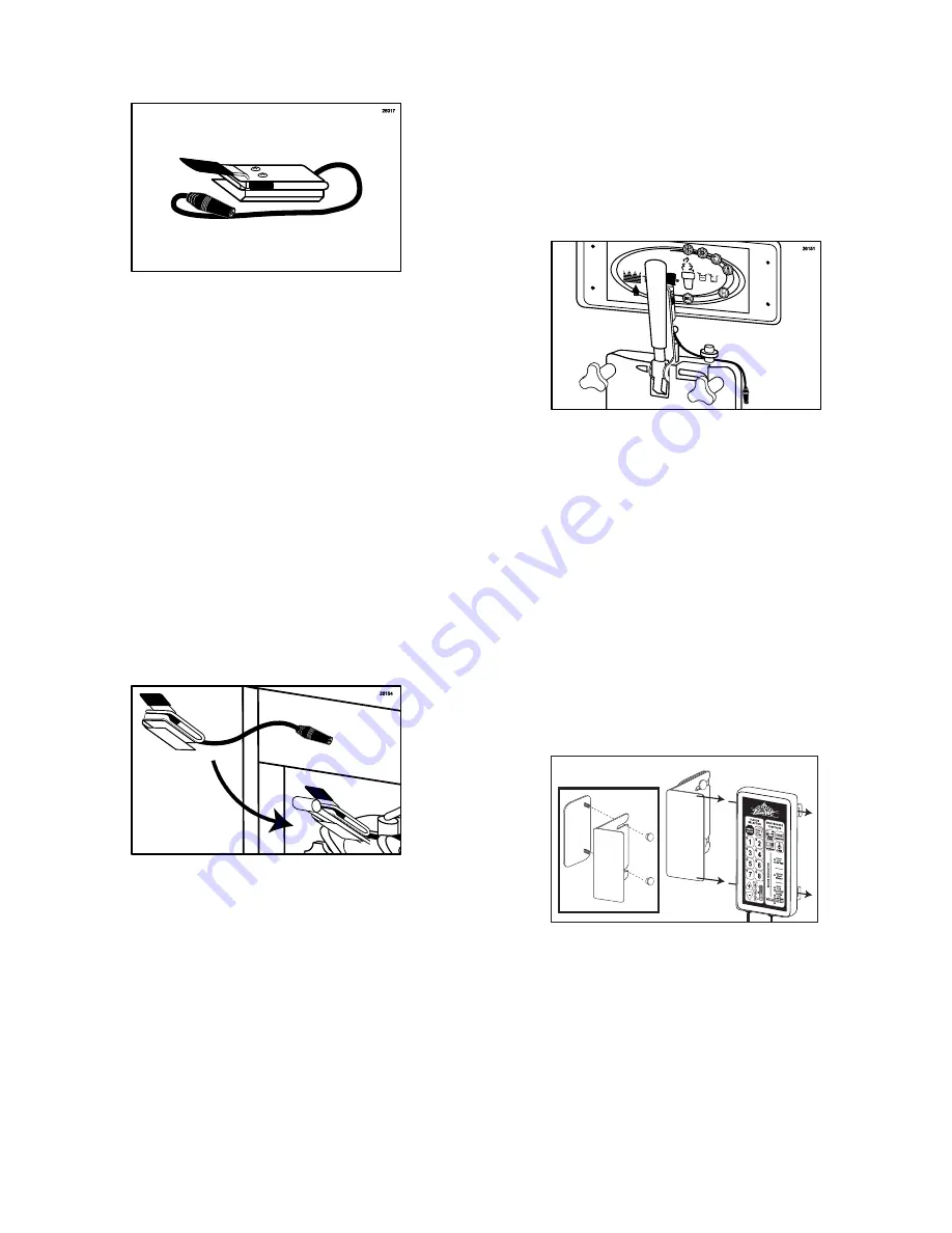
Installing the Spigot Switch Assembly 


Figure 116 


To activate the Flavor Burst

®

 system, a switch 

must be installed on the freezer draw-handle. 
Every FB 80D system ships with a standard 
Spigot Switch Assembly common to most 
freezers with flat handle bars. (See Figure 116.) 
 
Should your freezer have a round handle rod or 
a handle of unusual size or shape, this standard 
switch may not be suitable for your freezer 
model.  Contact your local distributor if the 
Spigot Switch included with your unit does not 
fit. 
 
1.  To install the standard Spigot Switch 

assembly to a flat handle, simply clip the 
Switch Bracket onto the handle and slide it 
up the handle until the switch is within 
grasping range. (See Figure 117.)   


Figure 117


NOTE:

  IF YOUR UNIT INCLUDES AN 

ALTERNATE SPIGOT SWITCH, REFER TO 
INSTRUCTIONS INCLUDED WITH IT FOR 
PROPER INSTALLATION. 
 

NOTE

:  THE SPIGOT SWITCH INSTALLED 

ON THE FREEZER SHOWN IN OTHER 
SECTIONS THROUGHOUT THIS MANUAL IS 

NOT

 THE STANDARD SPIGOT SWITCH 

ASSEMBLY AND IS ONLY FOR USE WITH 
THAT FREEZER OR SIMILAR MODELS.  (See 
Figure 118.) 


Figure 118 


Installing the Keypad and Keypad Mounting 
Bracket 
 

The Keypad is the control unit for the Flavor 
Burst

®

 system.  Normal operating functions are 

performed using the Keypad and the freezer 
draw handle.  The Keypad is attached to the 
freezer with the Keypad Mounting Bracket. 
 
1.  Slide the Keypad onto the main Bracket 

plate and assemble the two Bracket parts in 
the style that will best suit your freezer and 
daily operations.  One example is given in 
the figure below.  (See Figure 119.)   


26120


Figure 119


Summary of Contents for FB 80D Series

Page 1: ...unit with this manual It is important that the operator carefully review the warranty and installation documents accompanying the unit before using this system Any questions or concerns regarding the...

Page 2: ...urst syrup is stored within the equipment cabinet in 1 gallon disposable bags Proper syrup injection rate is maintained by adjusting the flavor level on the system keypad Components of the FB 80D syst...

Page 3: ...structions may result in serious electrical shock NOISE LEVEL Airborne noise emission does not exceed 70 dB A when measured at a distance of 1 0 meter from the surface of the machine and at a height o...

Page 4: ...o side of freezer 8 N A OUTER CABINET ASSEMBLY 1 Houses inner cabinet assembly 9 CAB 113 FLAVOR TRAY 8 Houses syrup bags 10 N A INNER CABINET ASSEMBLY 1 Houses syrup trays and bags 11 SAN 755 SANITIZE...

Page 5: ...4 General System Overview 13 2 1 3 5 6 15 14 10 8 11 12 9 7 17 16 4 26000 Figure 1...

Page 6: ...ows grip for opening front panel 6 FAS 2024 SCREW 2 Fastens handle to front door panel 7 RUB 618 RUBBER BUMPER W WASHER 4 Provides spacing between cabinet base and table 8 FAS 2014 8 32 X 1 2 PAN HEAD...

Page 7: ...6 Outer Cabinet 3 1 2 12 10 7 13 4 5 9 8 6 11 26001 Figure 2...

Page 8: ...ANEL 1 Attaches the bottom of the inner and side panels 10 FAS 2035 8 32 NUTS EXT LOCK WASHER 30 Secures screws to pump brackets and pumps 11 FAS 2024 8 32 X 1 4 PAN HEAD SCREWS 34 Fastens pump bracke...

Page 9: ...8 Inner Cabinet 26002 15 11 13 16 14 11 12 1 9 2 6 6 11 18 19 16 4 5 3 4 17 11 8 10 7 Figure 3...

Page 10: ...0 LINE COUPLER 2 Holds flavor lines in place 4C RUB 610 BAG CONNECTOR O RINGS 1 Provides extra tension between tube connectors 4D ROT 515 A 9 TUBE ASSEMBLY WAVE SPRING 1 Provides tension between tube...

Page 11: ...NGING BRACKET 1 Stores flavor line and Injector Drive Motor when not in use 12 MIS 3026 SURFACE RACEWAY 2 Attaches flavor lines to side of freezer 13 ADPT 8750 A CROWN ADAPTER WITH O RINGS 1 Attaches...

Page 12: ...ea Carries syrup from syrup bag to pump 2C TUB 811 TUBE SILICONE 188X 375 PE FB80 1 ea Connects barb fitment to tube port 2D FIX 1048 FITTING 1 4X1 4 BARB FB80 1 ea Connects syrup tube to silicone tub...

Page 13: ...12 Syrup Pump and Related Parts 26004 11 3 10 9A 9B 9 4 5 6 8 7 9C 2 2A 2C 2D 2B 1 1D 1C 1A 1G 1B 1E 1F Figure 5...

Page 14: ...TANK FITMENT 1 Connects flush tube to Sanitizer Tank 10C SYR 931 CLEAR TUBING 3 Transports sanitizer to sanitizer flush tubes 10D FIX 1046 FLUSH TUBE Y CONNECTOR 1 Splits sanitizer flush tube into two...

Page 15: ...14 Sanitizer Pump and Related Parts 1 2 2 9 13 12 11 8 3 4 5 6 7 15 14 14G 14B 14E 14C 14F 14A 14D 13 13 14H 14H 14H 14H 10 10C 10A 10B 10C 10C 10D 26005 Figure 6...

Page 16: ...ET ASSEMBLY 1 Mounts the Keypad to the freezer 4A MIS 3080 KEYPAD MOUNTING PLATE 1 Attaches to freezer to mount Keypad Bracket 4B MIS 3103 KEYPAD MOUNTING BRACKET 1 Holds Keypad in place 4C FAS 2023 A...

Page 17: ...16 Remote Module and Electronic Parts 4A 4 4B 4C 1 2 3 5 5 6 7 8 REVERSE SIDE 9 10 26006 Figure 7...

Page 18: ...RING 1 Creates tension to secure Adapter to Injector Head 2D RUB 640 FLAT ADAPTER GASKET 1 Provides sealed cavity inside Adapter 2E RUB 642 ADAPTER O RING 1 Creates tension to secure Adapter to freez...

Page 19: ...18 Maintenance Kit and Spare Parts Kit 1 2 1D 2I 2C 1A 2A 2B 2D 2E 2F 2H 2K 2J 2L 1C 1B 2M 2G 2N 26007 Figure 8...

Page 20: ...19...

Page 21: ...ROCEDURES This is typically performed at the close of the previous business day Sanitizing the Injector System 1 Prepare an approved sanitizer solution according to manufacturer s instructions 2 Place...

Page 22: ...s and will need to be replaced periodically Check for wear occasionally and always keep spares of these items on hand in the Spare Parts Kit 1 Place the Gear Cartridge into the Drive Assembly Gear Box...

Page 23: ...ad to purge any remaining product from the Injector Head See Figure 21 26250 Figure 21 Other items to check during opening procedures These steps do not necessarily need to be performed as part of the...

Page 24: ...23...

Page 25: ...llow these instructions to remove the Injector System from the freezer during closing 1 With a container under the dispensing spout press the WATER SYRUP FLUSH key on the Keypad to purge any remaining...

Page 26: ...et See Figure 28 26183 Figure 28 3 Rotate the Injector Head to unlock it from the Gear Box See Figure 29 26031 Figure 29 4 Remove the Gear Cartridge from the Gear Box See Figure 30 Figure 30 Sanitizin...

Page 27: ...acket may be disassembled for a more thorough cleaning if necessary See Figure 34 Figure 34 NOTE UNDER NORMAL OPERATING CONDITIONS IT IS NOT ADVISORY TO BRUSH OTHER AREAS INSIDE THE DRIVE ASSEMBLY GEA...

Page 28: ...service towels See Figure 39 Detergent CLEAN Water RINSE DRY 26014 Figure 39 11 The following do not need to be sanitized on a daily basis However inspect these areas and if necessary clean according...

Page 29: ...may change flavors periodically as desired 1 Mix approved detergent with warm water according to manufacturer s instructions Also prepare approved sanitizer solution according to manufacturer s instru...

Page 30: ...the bag to settle in the tray See Figure 46 Figure 46 9 Make sure the syrup bag is settled neatly into the tray and then install the loaded tray into the cabinet See Figure 47 26196 Figure 47 10 Clea...

Page 31: ...olution and or fresh product to be dispensed and press WATER SYRUP FLUSH to prime the syrup line See Figure 53 26251 Figure 53 17 Once syrup flows consistently from the Injector Head press CANCEL ENTR...

Page 32: ...31...

Page 33: ...cording to the product manufacturer s instructions This Clean In Place procedure is detailed in 3 phases 1 9 Tube Assembly Cleaning 2 Syrup System Cleaning and 3 Reassembly To ensure maximum results t...

Page 34: ...d sanitizer solution Allow these items to soak throughout the upcoming processes See Figure 60 26174 Figure 60 CIP Phase 2 Syrup System Cleaning NOTE THE FOLLOWING CLEAN IN PLACE PROCEDURE STEPS 8 22...

Page 35: ...h and clean the outer surfaces of the syrup bag fitment and the Connector with detergent water and a single service towel Then rinse and dry the parts using clean water and single service towels See F...

Page 36: ...E 19 While the Pump Flush procedure is running perform Steps 8 14 to sanitize the next Syrup Bag Connector Syrup Bag Adapter and syrup bag fitment NOTE YOU MAY CLEAN THE INJECTOR ASSEMBLY ACCORDING TO...

Page 37: ...26275 Figure 74 26 Remove the Syrup Line Manifold Manifold cap the Duckbill Check Valve and Coupler Body from the sanitizer solution and place on a sanitary tray to air dry See Figure 75 26091 Figure...

Page 38: ...ime the syrup system as instructed in Priming the Syrup System Priming the Syrup System Priming the syrups is necessary when first installing the flavors after the Clean In Place procedure when an ind...

Page 39: ...e Sanitizer Tank should be checked on a daily basis and refilled if the supply is low Replace the sanitizer solution with a fresh supply weekly and before performing the Clean In Place Procedure 1 Pre...

Page 40: ...ith the freezer door removed Therefore clean only as needed or when disassembling the freezer door for cleaning approximately every 2 weeks Replacement o rings and gasket are available in the Spare Pa...

Page 41: ...ean the freezer door and spout according to manufacturer s instructions before installing the Spout Adapter on the freezer door 9 Set the Adapter on a flat clean surface and then place the freezer doo...

Page 42: ...n approved sanitizer solution and soak for at least 1 minute See Figure 99 Figure 99 5 Remove the o rings and Injector Head and place them on a sanitary tray to dry See Figure 100 26092 Figure 100 6 P...

Page 43: ...e area with a single service towel and clean warm water and then wipe dry with a dry single service towel 4 Clean the outside and underside of the cabinet using detergent water and single service towe...

Page 44: ...nd clean warm water and then wipe dry with a dry single service towel 4 Reassemble the Keypad Mounting Bracket according to instructions Injector Assembly Suspension Bracket Figure 106 1 Remove the Br...

Page 45: ...service towel and warm water then dry with a dry single service towel 4 Reassemble the 9 Tube Assembly if necessary according to instructions Spigot Switch and Switch Bracket ELECTRICAL HAZARD DO NOT...

Page 46: ...izer solution from the Sanitizer Tank See Figure 111 26246 Figure 111 4 Repeat Steps 15 18 of the Clean In Place Procedure without sanitizer solution in the tank until the syrup lines are empty of san...

Page 47: ...cturers See the ALTERNATE PARTS AND KITS BY FREEZER MODEL section for more information Since the fitting is very tight install the Adapter with the freezer door removed Keep replacement o rings and ga...

Page 48: ...n grasping range See Figure 117 Figure 117 NOTE IF YOUR UNIT INCLUDES AN ALTERNATE SPIGOT SWITCH REFER TO INSTRUCTIONS INCLUDED WITH IT FOR PROPER INSTALLATION NOTE THE SPIGOT SWITCH INSTALLED ON THE...

Page 49: ...4 Remove the protective tape from the adhesive pad Attach the Keypad bracket assembly to the desired mounting area Ensure there is enough room between the Keypad assembly and the freezer face to slid...

Page 50: ...and slide the coupler casing down See Figure 125 Figure 125 3 Loosen the Lead s coupler nut and slide the connection onto the Cabinet slot See Figure 126 Figure 126 4 Tighten the coupler nut and the...

Page 51: ...Sanitizer Tank should be checked on a daily basis but only needs to be refilled if the supply is low 1 Prepare approved sanitizer solution according to manufacturer s instructions 2 Disconnect the san...

Page 52: ...ccording to manufacturer s instructions 2 Place the Gear Box Suspension Bracket Gear Cartridge and Injector Head in approved sanitizer solution and soak for 1 minute See Figure 137 26066 Figure 137 3...

Page 53: ...stalled on the freezer the Bracket should hold the Injector Assembly level horizontally with the Injector Head lined up directly under the Spout Adapter The Suspension Bracket is adjustable to fit man...

Page 54: ...OUTSIDE OF THE BRACKET ASSEMBLY NOTE THE HOOK OF THE UPPER BRACKET CAN BE FACING EITHER DIRECTION ACCORDING TO PREFERENCE See Figure 146 Figure 146 3 Hang the Suspension Bracket on the lower door post...

Page 55: ...jector Assembly so that the syrup lines are level with the connection at the Injector Head 1 Mix approved detergent with warm water according to manufacturer s instructions 2 Determine the approximate...

Page 56: ...room for the Drive Motor to hang properly 1 Mix approved detergent with warm water according to manufacturer s instructions 2 Determine the approximate area where the Bracket will be attached on the s...

Page 57: ...he lower back of the cabinet Once connected to the Cabinet and turned on the Microprocessor Module can remain on during normal operations It does not need to be turned off unless it is serviced or mov...

Page 58: ...167 8 The Keypad should confirm power up by sounding an audible startup tone and lighting the LED s on the Keypad Clean In Place CIP Procedure Perform the Clean In Place procedure as instructed in th...

Page 59: ...ly See Figure 168 Figure 168 3 Select the syrup flavor you wish to use then place the bag on the table with the fitment up and remove the dust cap See Figure 169 Figure 169 4 Lifting up with the bag f...

Page 60: ...SE DRY 26276 Figure 174 10 Using a spray bottle of approved sanitizer solution spray the syrup bag fitment and the Syrup Bag Connector Allow these parts to sanitize for at least 1 minute See Figure 17...

Page 61: ...EL ENTRY NOTE THE PUMP FLUSH FUNCTION WILL AUTOMATICALLY SHUT OFF AFTER 15 MINUTES NOTE YOU MAY WANT TO PROCEED WITH STEP 16 AS TIME ALLOWS DURING THE PUMP FLUSH FUNCTION IF AN ADDITIONAL FLAVOR NEEDS...

Page 62: ...61...

Page 63: ...te that particular syrup pump If the Syrup Bag Connector for that particular pump is connected to a syrup bag this function is used to prime that particular syrup pump and syrup line If the Syrup Bag...

Page 64: ...avor in a multi flavored serving in the Combo Timer mode It also shows the timing that is set for each serving size in the Timer mode The Increase and decrease keys control these levels in the graph T...

Page 65: ...graph represent 0 See Figure 182 26311 3 example Figure 182 3 Select 2 count the bars and record it as the second to last digit in the serving count Continue this process for keys 3 8 See Figure 183 2...

Page 66: ...ou pull the draw handle down to dispense product See Figure 187 26211 Figure 187 NOTE WHEN YOU PULL THE DRAW HANDLE DOWN TO DISPENSE THE SERVING PRESSING THE SWITCH LEVER AGAINST THE DRAW HANDLE START...

Page 67: ...ration See Figure 190 26280 Figure 190 2 Press and hold the SYRUP FLOW key for three seconds until the SYRUP FLOW ADJUSTMENT light is illuminated See Figure 191 26281 Figure 191 3 Press to increase th...

Page 68: ...flavor was set at a level 7 moving the bar up two levels in this mode will reset the 2 flavor to level 5 and the 6 flavor to level 9 See Figure 196 26286 Figure 196 8 Press the SYRUP FLOW key to exit...

Page 69: ...til the correct number of bar graph lights are illuminated See Figure 200 26292 WIDER LAYERS Figure 200 4 To decrease the timing for more narrower layers press the key until the correct number of bar...

Page 70: ...g to the freezer manufacturer s instructions 1 To adjust the small serving press the key To adjust the large serving press the key Two lights illuminate beside the size that is selected The medium ser...

Page 71: ...e small medium and large until the desired serving time for each size is set See Figure 207 26299 Figure 207 NOTE WHEN A PARTICULAR SIZE IS SELECTED THE SYRUP PUMP WILL STOP THE FLOW OF SYRUP AT THE S...

Page 72: ...71...

Page 73: ...tlet on back of the unit Power Cord is disconnected from power source outlet Keypad Cable is disconnected from receptacle on the back of unit The power fuse in the power entry module is blown The F 2...

Page 74: ...The Switch stereo plug and Keypad jack are unplugged or not fully engaged The Spigot Switch is faulty The Keypad switch cable is faulty If an integrated switch is used the switch lever is not activat...

Page 75: ...ording to instructions Replace the items Always keep replacements in the Spare Parts Kit Call for service or replace the Adapter Probable Cause The Switch stereo plug and Keypad jack are unplugged or...

Page 76: ...off center Replace the 9 Tube Assembly Probable Cause The Injector Head is not properly installed onto the Spout Adapter The lower black o ring is not present on the outside of the Spout Adapter The...

Page 77: ...ng the function is faulty The Sanitizer Tank is empty One or more of the water line connections are not fully engaged and therefore allowing air intake while the pump is operating The sanitizer pump i...

Page 78: ...opening DAILY CLOSING PROCEDURES page 24 Injector Head Gear Cartridge Drive Assembly Gear Box and Suspension Bracket 9 Tube Assembly opening Drive Motor Keypad Exposed Surfaces of the Cabinet SCHEDUL...

Page 79: ...tock inside the Spare Parts Kit for easy access PARTS REPLACEMENT SCHEDULE Part No Part Description Every 3 months Every 6 months Annually FLAVOR BURST COMPONENTS ADPT 101A Standard Spout Adapter with...

Page 80: ...tallation requirements This includes adapter kits adapters brackets and switches for various freezer models and manufacturers Please contact your local distributor or visit us online at www flavorburs...

Page 81: ...anel inside the cabinet Complete for quick reference when this information is requested 1 Model Number FB 80D _____________________________ 2 Serial Number ____________________________________ 3 Volta...

Reviews: