background image

OPERATIONS

FIKE CORPORATION

Page 30 of 43

SHP Product Manual

UL S2203

Rev. No: 3, 04/02

Manual P/N: 06-130

FM 0Z8A0.AY

5.4

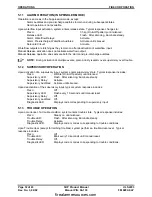
OUTPUTS DISABLED MODE

Holding silence switch active, then momentarily pressing reset switch puts system into the  “Outputs
Disabled Mode”.   A system in the “Outputs Disabled Mode” has:
     * Output circuits 1-5 disabled from activation

* Alarms Silenced LED is ON.

     * Trouble LED flashing @ 2 second rate

* Local piezo stays off during alarms. 

     * Trouble relay2 activated (but not Relay4). 
     * All other system operations (Relays, piezo, LED’s, etc.) should operate as typical.

This mode is designed to allow partial system checkout without activation of audible circuits.

5.5

SUPERVISORY AND TROUBLE STATUS LED’S

Event

LED

Piezo

Upon supervision alarm or trouble

Flashes (2 second rep)

On

Upon silence acknowledge

Steady

Off

Upon event clear

Blinks (10 second rep)

Off

Upon event recurrence

Flashes (2 second rep)

On

Flashes occur for one second every 2 seconds.  Blinks occur only once every 10 seconds.
Piezo operation is: {Alarm Events: Chirp}      {Supervisory: Warble}      {Trouble: On steady}
Piezo priority is in same order; alarm events over supervisory events over trouble events.

5.6

LATCHING VERSUS NON-LATCHING TROUBLES

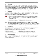
Input circuit troubles, Bad A-D channel, and Low DC power are latching troubles.  All other troubles are
non-latching (upon restoration to a normal condition).  If all troubles are non-latching and all have cleared,
system delays 5 seconds, then performs a trouble-clear-reset. Upon clearing of non-latching troubles
(including AC power loss), their diagnostic LED code will flash and the trouble status LED will blink every 10
seconds until manual system reset.

5.7

WATERFLOW ALARM OPERATION

The waterflow input available in the “sprinkler mode” operates similar to a manual release in that it forces
the system immediately into the release state.  The waterflow output is only activated after activation of the
waterflow input.

5.8

SUPERVISION RESPONSE TIMES

Supervision of circuits is designed to be within these time intervals:

Detector, Contact Input wiring

 1 second

Audible wiring:  

 8 seconds

Release circuit wiring:

 5 seconds

24V Buss Power

 5 seconds

Battery wiring:

30 seconds

Supervision is delayed up to 15 seconds immediately after a reset or power-up.

5.9

LOW POWER CONDITIONS

The system is designed to suspend detector operation if AC power is missing and system battery power
falls below 19V (“d” trouble) since detector operation is not guaranteed at these voltages.  System field
design and maintenance should be such to prevent this occurrence.  After occurrence, restarting the system
requires return of AC power in conjunction with a manual system reset.

System will register brown-out trouble if AC voltage is less than approximately 85% of rating.  Both AC
power and battery power are enabled at all times, allowing each to supplement the other. Partial fall-out of
one power source permits the other to provide most of the needed power.  If auxiliary input power is
provided, it likewise is enabled at all times.

firealarmresources.com

Summary of Contents for SHP 10-051

Page 1: ...Product Manual Conventional Fire Alarm Suppression System Manual P N 06 130 Rev No 3 04 02 P N 10 051 firealarmresources com ...

Page 2: ...firealarmresources com ...

Page 3: ...s a one year limited manufacturer s warranty on this product The standard warranty is printed in each Marketing Price List All warranty returns must be returned from an authorized Fike Sales outlet Contact Fike s Marketing Department for further warranty information Fike maintains a repair department that is available to repair and return existing electronic components or exchange purchase previou...

Page 4: ...firealarmresources com ...

Page 5: ...nclosure Specifications 19 4 0 Installation 21 4 1 Enclosure Installation 21 4 2 Power and Field Wiring 22 4 3 Wiring Verification 23 4 4 System Module Installation 23 4 5 System Configuration 23 4 6 Wiring Diagrams 24 25 4 7 Circuit Configuration 26 27 4 8 Initial Power Up 28 4 9 Complete Field Wiring 28 4 10 Checkout System 28 4 11 Releasing Hardware 28 5 0 Operations 29 5 1 User Switch Interact...

Page 6: ...203 Rev No 3 04 02 Manual P N 06 130 FM 0Z8A0 AY 6 0 Servicing 33 6 1 Checkout 33 6 2 Maintenance 33 6 3 Troubleshooting 33 36 Appendix 1 37 Battery Calculations 37 38 Appendix 2 39 ULC Operation 39 Appendix 3 41 System Operation Posting 41 Index 43 firealarmresources com ...

Page 7: ...the inside door left side there should be a sticker with an indication of the sales outlet who sold the system If you can not locate the sales outlet please call Fike Customer Service for locating your nearest sales outlet or go to our web site at www fike com If you are unable to contact your installing sales outlet or you simply do not know who installed the system you can contact Fike Product S...

Page 8: ...d and responding properly The system remains in normal state until a trouble condition occurs Notification Appliance A fire alarm system component such as a bell horn speaker light or textual display that provides audible tactile or visible output or any combination thereof The device notifies building occupants of system status This manual interchanges the terms notification and audible appliance...

Page 9: ... Reset of the system overrides this value Supervisory State Supervisory Yellow LED ON Piezo Warble The supervisory state occurs upon activation of a supervisory input circuit The supervisory state is non latching and will follow the status of the supervisory input contact Trouble State Trouble Yellow LED ON Piezo Constant The trouble state occurs upon any detectable condition which could impair sy...

Page 10: ...omponents Handle the electronics by the edges only and avoid touching the integrated components Keep the electronics in the protective static bags it was shipped in until time for installation Always ground yourself with a proper wrist strap before handling the module s If the installer is grounded at all times damage due to static discharge will not occur If the module requires repair or return t...

Page 11: ...Approval Agency File Number Underwriters Laboratories S2203 Type Local Remote Station Central Station PPU Service Type A Automatic Fire Alarm M Manual Fire Alarm WF Water flow alarm SS Sprinkler Supervisory Service Releasing DACT Type Signaling Non coded Underwriters Laboratories of Canada ULC CS401 CS770 25168 25169 Factory Mutual FM OZ8A0 AY California State Fire Marshall CSFM 7165 0900 114 City...

Page 12: ...tive Signaling Systems UL 268A Smoke Detectors for Duct Applications UL 346 Waterflow Indicators for Fire Protective Signaling Systems UL 464 Audible Signaling Appliances UL 521 Heat Detectors for Fire Protective Signaling Systems UL 1481 Power Supplies for Fire Protective Signaling Systems UL 1638 Visual Signaling Appliances UL 1971 Visual Signaling Appliances Factory Mutual FM Standards FMRC 101...

Page 13: ...AH to 18 AH battery options up to 90 hours standby Enclosure Steel enclosure 21 high by 14 35 wide by 4 deep Back box dimensions Enclosure is equipped with a 50 wide lip to facilitate flush mounting Removable door for easy installation Enclosure is available in Red or Gray Initiating Device Circuits Up to two Style B initiating device circuits capable of sequential alarm cross zone or single detec...

Page 14: ...OVERVIEW FIKE CORPORATION Page 8 of 43 SHP Product Manual UL S2203 Rev No 3 04 02 Manual P N 06 130 FM 0Z8A0 AY This page intentionally left blank firealarmresources com ...

Page 15: ...trol System c R red G gray p 1 120VAC 2 208 or 240VAC 10 2171 SHP Controller Printed Circuit Board 10 2172 Class A Input Module 10 2176 SRM4 Relay Module 10 2190 b Battery Assembly AH selection b 1 7 AH 2 18 AH 10 051 SHP Control System Includes the main controller with transformer and AC terminal block inside steel enclosure red or gray The enclosure door is equipped with a standard Fike keylock ...

Page 16: ...dry contact relays which activate upon selected events per the configuration switches The SRM4 Relay module mounts directly onto the SHP Controller at RM4 utilizing four nylon stand offs supplied with the module 10 2190 B Battery Assembly Batteries are required for alarm systems for maintaining emergency back up power Two each 12V batteries are required and are to be wired in series for maintainin...

Page 17: ...e 67 1010 67 1035 220 Ω 6 Base SDR or Cross Zone Only 67 1017 67 1037 220 Ω 4 Base SDR or Cross Zone Only 63 1012 430 Ω Relay Base NOTE If using LED graphic it is required to use the older type bases Please note on the order Using conventional graphic with panel do not substitute bases 63 1024 Photoelectric Detector The photoelectric smoke detector is well suited for fires ranging from smoldering ...

Page 18: ... F Rate of Rise The fixed temperature rate of rise heat detector features electronic circuitry to close normally open contacts when the fixed temperature is reached or when the rate of rise is greater than 12 F minute Warning Heat detectors are for property protection only not life safety 67 1034 6 Base Electronics free 6 base with plastic tamper lock lug Contains a 430Ω resistor Can be used for S...

Page 19: ... 06 019 Conventional Graphic Annunciator Provides graphic point annunciation for detectors 10 2256 Digital Alarm Communicator Transmitter DACT The SHP panel is capable of communicating to a Central Station via the DACT optional The DACT monitors the relay outputs of the SHP It is necessary to program the DACT with the 10 2257 programmer and 10 2258 cable or 10 2259 modem and 06 151 software 10 183...

Page 20: ...rmer 208 240 VAC 02 3938 120 VAC Varistor 02 1532 208 240VAC Varistor 02 2275 Mounting hardware for SRM4 or Class A Module each uses 4 ea 3 8 nylon spacer 02 4008 250V 12 Amp Fuse F1 02 3945 Releasing circuit end of line EOL assembly 2 7K 10 2316 Input circuit EOL assembly 4 3K 10 2318 Output circuit EOL assembly 2 0K 10 2319 Capacitor 100uF 50V for testing battery circuit 02 3774 Power terminal P...

Page 21: ... BAT COM Standby Battery 20 4 28VDC non power limited Sealed lead acid batteries only 18 amp hour maximum Maximum supply current 8 amps 27VDC Maximum charge current 1 5 amps 27VDC 4 5 COM AUX Optional Auxiliary input power supply 20 28VDC non power limited Requires regulated source UL listed for fire protective signaling Maximum supply current 8 amps 24VDC Maximum ripple 0 100 Volts rms NOTE Stand...

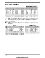
Page 22: ... LED graphic it is required to use the older type bases as listed in Section 3 2 Please note on the order Using conventional graphic with panel do not substitute bases DETECTOR COMPATIBILITY NOTE Use Hochiki detectors with Hochiki bases and System Sensor detectors with System Sensor bases HOCHIKI SYSTEM SENSOR Fike P N Type Mfg P N Fike P N Type Mfg P N 63 1024 Photoelectric SLR 24 63 1015 Photoel...

Page 23: ...Y Maximum wire resistance limited by the chart below 2 0 K End of line resistor EOL 2 Amps maximum Listed for use with any 18 30VDC polarity reversal indicating appliance listed for fire alarm signaling Fike tested indicating appliances compatible with the SHP are detailed in the Fike compatibility document P N 08 186 15 16 Agent Release Module Suppressant Agent Release output 24 VDC nominal Power...

Page 24: ...VAC pf 35 10 2172 Class A Input Module Optional module that provides the ability to wire input circuits in a Class A NFPA Style D configuration If the module is installed on the SHP any of the circuits can be converted back to Class B by clipping the associated resistor R1 R4 R1 for Input 1 R2 for Input 2 etc Maximum wire resistance total for the input circuits remain the same as listed in P2 Inpu...

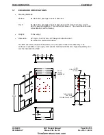
Page 25: ...movable door with full swing Weight 15 lbs empty Dimension 22 High x 15 25 Wide x 4 5 Deep with attached door See below for precise dimensions The SHP enclosure includes the back box door and power transformer assembly The enclosure is available in red or gray color options Optional modules are shipped separately and must be installed in the field 22 00 14 35 2 25 12 13 FOR INSTALLATION 2 EA SIDE ...

Page 26: ...EQUIPMENT FIKE CORPORATION Page 20 of 43 SHP Product Manual UL S2203 Rev No 3 04 02 Manual P N 06 130 FM 0Z8A0 AY This page intentionally left blank firealarmresources com ...

Page 27: ...e exact temperature ratings of the equipment Do not install in an environment that exceeds these temperature ranges The SHP Control System enclosure is not fire rated DO NOT INSTALL ON or IN A FIRE RATED WALL The control panel should be installed so the viewing window is approximately 60 above the floor The back box can be surface or flush mounted as desired For surface mounting utilize the four t...

Page 28: ...tch Wiring Criteria Abort input circuits are to be wired only with momentary contact switches so they cannot be left activated without human interaction AC Power Chassis Wiring AC power must originate from a dedicated 10 20 amp circuit at the main building power distribution center The circuit breaker must be equipped with a lockout mechanism and be clearly labeled as a Fire Protection Control Cir...

Page 29: ...5 2 0 Audibles 1 3 Max Ωs 24 12 8 6 4 8 4 0 3 0 2 4 1 6 1 2 Agent Release Max Ωs 35 35 35 35 35 35 35 35 35 35 Solenoid Max Ωs 12 6 4 3 2 4 2 0 1 5 1 2 0 8 0 6 4 4 SYSTEM MODULE INSTALLATION Install system modules after the enclosure has been installed and cleaned of all dust and debris Modules include the appropriate mounting hardware Prior to handling or installing any modules appropriate anti s...

Page 30: ... AUXILIARY OUTPUT RES P3 6 AUDIBLE 1 7 8 9 10 SW3 P5 P4 NO ALARM RELAY TROUBLE RELAY NC C NO 0 OHM JUMPER R26 R27 0 OHM JUMPER NC C 32 POWER LIMITED 31 30 29 28 27 AUDIBLE 2 AUDIBLE 3 11 12 LIMITED 13 14 MODULE AGENT RELEASE SOLENOID 15 16 17 18 SILENCE ARM DISABLE SW4 CIRCUITS RELEASE INPUT 1 P2 19 20 P6 INPUT 2 INPUT 3 LIMITED 21 22 POWER 23 24 INPUT 4 25 26 RESET AC NORMAL ALARM PRE DISCHARGE R...

Page 31: ...ociated resistor R1 R4 removed from that circuit 65 R E LA Y 3 65 66 64 63 62 48 58 RELA Y 6 RELA Y 5 61 60 59 57 56 55 RELA Y 4 54 53 52 51 50 49 RELA Y 3 47 46 45 C 44 43 NC NO P1 HD NO NO NO NO NC NC NC NC C C C C NC NO C NO NC C C NC NO DEFA ULT STA T ES SHO W N V ERIFY ST A T ES PER CO NFIG URA T IO N SELECT ED A LA RM Pre DISCHA RG E A BO RT RELEA SE R4 R1 P6 P2 REV 10 2172 A SSY K1 K2 K3 K4...

Page 32: ...charge Pre discharge Trouble Trouble Non Rel 5 Release Release Waterflow Waterflow Non Rel 6 Abort Superv Abort Supervisory Supervisory Non Italicized Supervisory Manual Release options are activated when switch S8 On Clip the pertinent 0 ohm jumper if using 0 ohm bases or contact closure devices Relays are dry contact outputs which activate up on the given states listed above Relays 1 2 are on SH...

Page 33: ...0 Min S7 0 1 ARM III Operation 12 volt solenoid operation Not Applicable Unused ABORT TYPES These abort types are programmable via SW3 configuration switches S3 S4 Countdown does not begin until the system is in the predischarge state TYPE 1 The abort is effective only if active upon entry into predischarge state Countdown continues during abort activation Upon abort deactivation during predischar...

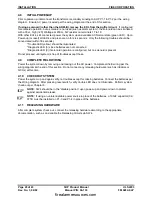
Page 34: ...Diagnostic LED 9 if solenoid operation is configured but no solenoid is present Do not proceed until system is free of troubles except these 4 9 COMPLETE FIELD WIRING Power the system down by removing and locking out the AC power Complete all field wiring per the wiring diagram at the end of this section Do not connect any releasing hardware such as initiators or GCA s at this time 4 10 CHECKOUT S...

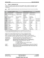
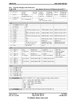
Page 35: ...udible 2 6 Open 6 Shorted Audible 3 7 Open 7 Shorted Agent Release Module 8 Open 8 Shorted or initiator open Solenoid 9 Open 9 Shorted System 0 Ground Fault Abort Input A Valid Abort Battery Failure B Missing Battery 2 nd Alarm Active C Input Circuit 1 C Input Circuit 2 System Voltage D Low Voltage 19VDC Microcontroller E Intelli Fet lost E 5VDC Reference A D Failure Invalid Abort F Abort prematur...

Page 36: ...lays 5 seconds then performs a trouble clear reset Upon clearing of non latching troubles including AC power loss their diagnostic LED code will flash and the trouble status LED will blink every 10 seconds until manual system reset 5 7 WATERFLOW ALARM OPERATION The waterflow input available in the sprinkler mode operates similar to a manual release in that it forces the system immediately into the...

Page 37: ...Alarm Pre discharge relays also remain active Alarm Audible Off if not already silenced Pre discharge Audibles Activate Unsilence if silenced Release Audibles Activate until silenced Release Circuits Activate AgtRel or solenoid circuit Upon activation of the Abort Switch system responds with a trouble condition if it is not a valid abort time While activated during a valid abort time typical syste...

Page 38: ...uble 5 12 SUPERVISORY OPERATION Upon activation of a supervisory input system enters supervisory state Typical response includes Piezo Warble On Off pattern until silenced Supervisory LED Flash After silencing illuminate steady Supervisory Relay Activate Supervisory Audibles Activate until silenced Upon deactivation of the supervisory input typical system response includes Piezo Off Supervisory LE...

Page 39: ... to be tested install a flashbulb P N 02 3799 in place of the initiator GCA Do not connect initiators GCA to ARM III if any ground faults are present on the system 2 Follow ARM III manual 06 106 for safety considerations and ARM III wiring NOTE Use the Arm Disable Switch SW4 to disable the Agent Release and Solenoid circuits during system checkout and maintenance As a minimum place SW4 in the disa...

Page 40: ...OPEN 4 92mA 0 983V SHORT 14 6mA 2 93V 16 ARM 27 9V OPEN 27 9V SHORT 27 9V 17 SOL 24V ASCO 7 5mA 0 273V 12V 0 251V 7 63mA OPEN 2 43mA 0 975V OPEN 2 37mA 0 985V SHORT 8 62mA 0 081V SHORT 8 12mA 0 181V 18 SOL 24V ASCO 0V 12V 0V P2 19 INPUT 1 27 8V OPEN 27 9V ALM 27 7V ALM2 27 6V 20 INPUT 1 0 439V 6 3mA OPEN 0 237V 3 4mA ALM 1 338V 18 83mA ALM2 4 3V 62 8mA 44mA w low 24V 21 INPUT 2 26 3V OPEN 26 3V AL...

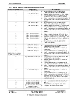
Page 41: ...fy correct value EOL Resistor 4 3 K Yellow Orange Red 5 6 7 NOTE The 6 is often confused with letter b Audible Circuit 1 open Audible Circuit 2 open Audible Circuit 3 open Verify correct value EOL Resistor 2 K Red Black Red has been installed Measure field wiring resistance reference Section 4 2 Verify all field devices are installed properly Remove field wiring and install a 2K resistor at panel ...

Page 42: ...erify charger voltage Reference Section 6 3 1 C 2 nd Alarm active on input 1 if using 430Ω bases Always activates on first alarm if using 220Ω or 0Ω devices Input circuit 1 C 2 nd Alarm active on input 2 if using 430Ω bases Always activates on first alarm if using 220Ω or 0Ω devices Input Circuit 2 d Low Voltage 19 volts Reference Section 5 9 Low Power Conditions Check AC and DC power input E Inte...

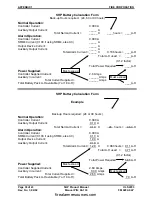
Page 43: ...rrent can each be calculated as the sum of A SHP controller current B SRM4 current for relays activated while in alarm C Output current to activated indicating devices D Auxiliary current from Aux Power Out circuit Module Type Module Current Consumption 10 2171 Controller 0 090 Amps 10 2172 Class A Module 0 000 Amps 10 2176 SRM4 Module 0 000 Amps 0 100A while in alarm Normal operation power in Amp...

Page 44: ...rrent 2 6 Amps Auxiliary In current ______ Amps Must exceed Total Current Supplied ______ Amps Total Battery Pack A H available 7 or 18 A H ____A H SHP Battery Calculation Form Example Back up Hours required 24 or 90 hours Normal Operation Controller Current 0 090 A Auxiliary Output Current 0 10 A Total Normal Current 0 19 X 24 hours 4 6 A H Alarm Operation Controller Current 0 090 A SRM4 Current ...

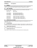
Page 45: ...G 2 Gray enclosure with 208 240 VAC input 10 051 CN R 1 Controller red enclosure 120 VAC input 10 051 CN R 2 Controller red enclosure 208 240 VAC input 10 051 CN G 1 Controller gray enclosure 120 VAC input 10 051 CN G 2 Controller gray enclosure 208 240 VAC input 3 0 OPERATIONAL CHANGES Three changes to the functionality of the system were incorporated in the Canadian version The changes are as fo...

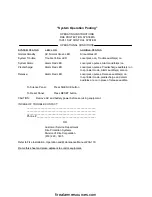
Page 46: ...roduct Manual UL S2203 Rev No 3 04 02 Manual P N 06 130 FM 0Z8A0 AY System Operation Posting on the next page is offered without headers or footers so that the sales outlet may make copies to post adjacent to control equipment firealarmresources com ...

Page 47: ...se audible s on In sprinkler mode predischarge and alarm audibles are on in place of release audible To Silence Panel Press SILENCE button To Reset Panel Press RESET button CAUTION Remove AC and battery power before servicing equipment IN CASE OF TROUBLE CONTACT __________________________________________________ __________________________________________________ ___________________________________...

Page 48: ...firealarmresources com ...

Page 49: ...losure 21 M Maintenance 33 Manual Release 32 O Outputs Disabled Mode 30 P Piezo 30 32 Power Calculations 38 Power Limited 22 Pre discharge 2 26 27 31 32 R Relays 31 Release 1 2 3 6 7 12 13 15 16 17 25 26 27 29 30 31 32 33 35 40 Reset Switch 29 S Sequential 2 3 12 16 25 26 Silencing 29 31 Solenoid 27 SPECIFICATIONS 15 19 SRM4 7 9 10 14 18 22 23 25 37 38 Status LED s 31 System Check Out 33 T Trouble...

Page 50: ...firealarmresources com ...

Page 51: ...firealarmresources com ...

Page 52: ...704 South 10 th Street P O Box 610 Blue Springs Missouri 64013 U S A 816 229 3405 Fax 816 229 0314 http www fike com firealarmresources com ...
Reviews: