


INSTALLATION
FIKE CORPORATION
Page 26 of 43
SHP Product Manual
UL S2203
Rev. No: 3, 04/02
Manual P/N: 06-130
FM 0Z8A0.AY
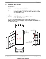
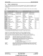
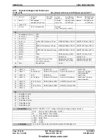
4.7
CIRCUIT CONFIGURATION
These columns define four basic operation modes selected by SW3. Position S1 (suppression versus
sprinkler) and S2 (sequential versus cross-zone detection). Switch position S7 and S8 allow further
customization.
NOTE:
The Agent Release Module circuit and the Solenoids circuit can’t be used concurrently.
S1:
Suppression Mode (S1 = Off)
Sprinkler Mode (S1 = On)
S2:
Sequential (Off)
Cross-Zone (On)
Sequential (Off)
Cross-Zone (On)
Silenceable
In #1 *
Sequential Det.
Cross-Zone Det.
Sequential Det.
Cross-Zone Det.
In #2 *
Seq. Det./
Supervisory
Cross-Zone Det.
Seq. Det. /
ManRel
Cross-Zone Det.
In #3
Manual Release
Manual Release
Waterflow
Waterflow
In #4
Abort In
Abort In
Supervisory
Supervisory
Aud #1
Alarm
Alarm
Alarm
Alarm
Silenceable
Aud #2
Pre-discharge
Pre-discharge
Predis /
Superv
Predis /
Superv
Silenceable
Aud #3
Release
Release
Waterflow
Waterflow
Silenceable
Agt Rel
ARM (S7 = Off)
ARM (S7 = Off)
Disabled
Disabled
Non
Sol
Solenoid (S7 = On)
Solenoid (S7 = On)
Solenoid
Solenoid
Non
Rel #1
Alarm
Alarm
Alarm
Alarm
Non
Rel #2
Trouble
Trouble
Trouble
Trouble
Non
Rel #3
Alarm
Alarm
Alarm
Alarm
Non
Rel #4
Pre-discharge
Pre-discharge
Trouble
Trouble
Non
Rel #5
Release
Release
Waterflow
Waterflow
Non
Rel #6
Abort/
Superv
Abort
Supervisory
Supervisory
Non
Italicized
Supervisory/Manual Release
options are activated when switch S8 = On
* Clip the pertinent 0 ohm jumper if using 0 ohm bases or contact closure devices.
Relays are dry contact outputs which activate up on the given states listed above.
Relays 1-2 are on SHP controller. Relays 3-6 are on optional SRM4 relay module.
Alarm, Pre-discharge, Release, and Waterflow relays are latching (do not clear until reset).
Abort, Supervisory, and trouble relays reflect current system status (except for latching troubles).
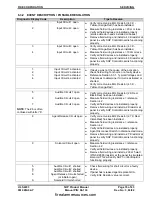
Sequential Det:
Sequential Zone detection circuit as described in Section 1.4.
Cross-Zone Det:
Cross-Zone detection circuit as described in Section 1.4.
Superv(isory):
Supervisory contact monitoring input circuit or indicating circuit.
Manual Rel:
Manual Release contact monitoring input circuit. Overrides aborts.
Waterflow:
Waterflow contact monitoring input circuit. Activates:
a.) solenoid output
b.) Audibles: Waterflow, alarm, and pre-discharge
c.) Relays: Waterflow and alarm
Abort In:
Abort contact monitoring input. Abort definitions are at the end of this section.
ARM:
Release circuit to fire GCA via Agent Release Modules (Fike P/N 10-1832).
Solenoid:
Solenoid release circuit used with either two 12V Fike CO2 solenoids or listed
industry 24VDC solenoids.
firealarmresources.com
Summary of Contents for SHP 10-051
Page 2: ...firealarmresources com ...
Page 4: ...firealarmresources com ...
Page 48: ...firealarmresources com ...
Page 50: ...firealarmresources com ...
Page 51: ...firealarmresources com ...