SAFETY AND CONTROL DEVICES
Safety thermostat
The manufacturer will not be liable for any
damage or injury resulting from failure to
observing the following rules.
The appliance is equipped with a manual reset safety
thermostat that interrupts heating when the operating
temperature exceeds the maximum permitted value.
To restore appliance operation press the thermostat
reset button. This procedure must only be carried out
by a qualified, authorized technician.
2. INSTRUCTIONS FOR INSTALLATION
REMINDERS FOR THE INSTALLER
Read th is manual carefully. It provides important
information for safe installation, use and maintenance
of the appliance.
The manufacturer will not be liable for any
damage or injury resulting from failure to
observing the following rules.
Identify the specific appliance model. The model
number is detailed on the packing and on the appliance
dataplate. The appliance must be installed in a well
ventilated room. Do not obstruct any air vents or
drains present on the appliance. Do not tamper with
appliance components.
REFERENCE STANDARDS AND LAWS
Install the appliance in accordance with the safety
standards in force in the country.
UNPACKING
Check the state of the packing and in the event of
damage, ask the delivery person to inspect the goods.
Remove the packing.
Remove the protective film from the outer panels.Use
a suitable solvent to remove any residual adhesive
from the panels.
POSITIONING
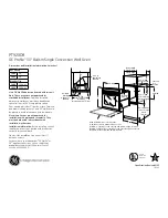
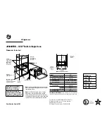
The overall dimensions of the appliance and the
position of connections are given on the installation
diagram at the start of this manual. The appliance is
not suitable for integrated installation. Position the
appliance at least 10 cm. from adjacent walls. This
distance can be reduced in the presence of non-
combustible walls or heat-insulated walls.
The appliance has no moving parts which could
affect the stability, therefore, are not provided for
locking elements to the ground.
CONNECTIONS
The position and dimensions of connections are given
in the installation diagram at the end of this manual.
Connection to the water supply
The appliance must be connected to a potable water
supply (max 3S°c.) . The water inlet pressure must
be between 1, 5 - 3 bar. Use a pressure reducer if
the inlet pressure is above the maximum permitted
!
!
level. Install a mechanical filter and a shut-off valve
upstream of the appliance in an easily accessible
point. It is necessary to have a supply of drinking
water with hardness <10 of to avoid circuit blockage.
Make sure the water circuit is free of ferrous particles
before connecting the filter and the appliance. Seal
any unused connectors with a plug. Once the
appliance has been installed, check for gas leaks at
the connection points.
Installation of a water softener is
recommended to avoid limestone deposit.
Water discharge
Water discharge is located in the lower part of the
oven and is to be connected to a rigid pipe, the
diameter of which should f it the discharge connection.
The down flow pipe must be fitted at least 20 cm,
underneath the attachment. Any discharge blockage
can be the cause of any bad odours in the baking
chamber or of any steam coming out of the door.
ELECTRICAL CONNECTIONS
Check that the appliance is designed to operate at
the voltage and frequency of the power supply
present on site. Check the details given on the
appliance data plate.
Install upstream of the equipment in an easily
accessible place, an all-pole disconnecting device
with a contact gap of allowing full disconnection
under the conditions of overvoltage category Ill.
A flexible rubber cable with insulation specifications
not lower than type H05 RN-F must be used for
connection. Connect the power supply cable to the
terminal board as shown in the wiring diagram supplied
with the appliance. Secure the power supply cable
with the cable clamp. Protect the power supply cable
on the outside of the appliance with a rigid plastic or
metal pipe.
PROTECTIVE EARTH AND EARTH BONDING
CONNECTIONS
Connect the appliance to an efficient ground circuit.
Connect the earth conductor to the terminal with the
symbol next to the main, terminal board. Connect
the metal structure of the appliance to the equipotential
node. Connect the conductor to the terminal with the
symbol pIaced on the outside of the rear panel.
COMMISSIONING
Following installation or any maintenance operations,
check appliance operation. ln the event of any
malfunction, consult the next Paragraph
"Troubleshooting".
ELECTRIC EQUIPMENT
Switch on the appliance as directed in the instructions
and reminders for use given in Chapter
" I N S T R U C T I O N S F O R U S E " a n d c h e c k :
- the current values of each phase.
- the correct operation of the heating elements.
- the regularity that your lights are bright.
- the regularity of operation of the engine.
!


