Fagor
M
odular Drives and Motors
Q
uick
R
eference. Ref.2104
MQR-73/84
Power-up procedure
Apply power from mains to connector X1 of the APS-24 (or to X3
of the XPS or PS-25B4). It will supply 24 Vdc to each drive
module drives are OK, the power supply module. Each module
runs an internal test. If the test is successful, the DR.OK contacts
close. If all the drives are OK, the power supply closes its
“SYSTEM OK” contact.
Push ON button. This supplies power from mains to the power
supply module, “charges” the power bus with a soft start,
activates the SYSTEM SPEED ENABLE of the power supply and
the DRIVE ENABLE of each drive.
Activate the control input SPEED ENABLE of each drive from the
CNC. The motor can now follow the velocity command.
Emergency line
The - KA1 relay confirms that the system is mechanically and
electrically in working condition.
Error reset
This circuit configuration joins the error reset and the system power-
up in a single push-button.
Control from CNC
The CNC enables each axis and confirms the SPEED ENABLE
signal to each drive by means of KA4, KA5, KA6 and KA7.
Stop
When the emergency line breaks or the OFF or - S1 keys are
opened, the control circuit of the drives must keep on working to
brake the motors, and the DRIVE ENABLE signal must be kept
active (24 Vdc). The FAGOR APS-24 (or the XPS, RPS or PS-25B4
auxiliary supplies) output power keep the power to the control
circuits, and the DRIVE ENABLE signals are kept active while
braking, by dela ying the deactivation of - KA3.
Remember that:
The control circuits of compact drives as well as RPS, XPS and PS-
25B4 power supplies are powered at 24 Vdc by an internal auxiliary
power supply. PS-65A power supplies will need an external APS-24
auxiliary power supply to power them because they do not have one
integrated into them.
For the AXD...-L modular drives designed for 200/240 Vac line
voltages (see “-L” in the commercial reference), install and supply the
PS-37-L main power supply with a three-phase line voltage of
200/240 Vac. The system also needs an ex24 Vdc auxiliary
power supply for the control circuits, since there is no integrated
power supply.
HOLDING BRAKE CONTROL
In some applications (e.g. the vertical Z axis on a milling machine) a
electromechanical holding brake is used on the rotor of the motor.
Hence, the brake holds the rotor when loses voltage at its terminals.
When the machine is out of service, the brake locks up the vertical Z
axis to keep it from falling due to gravity.
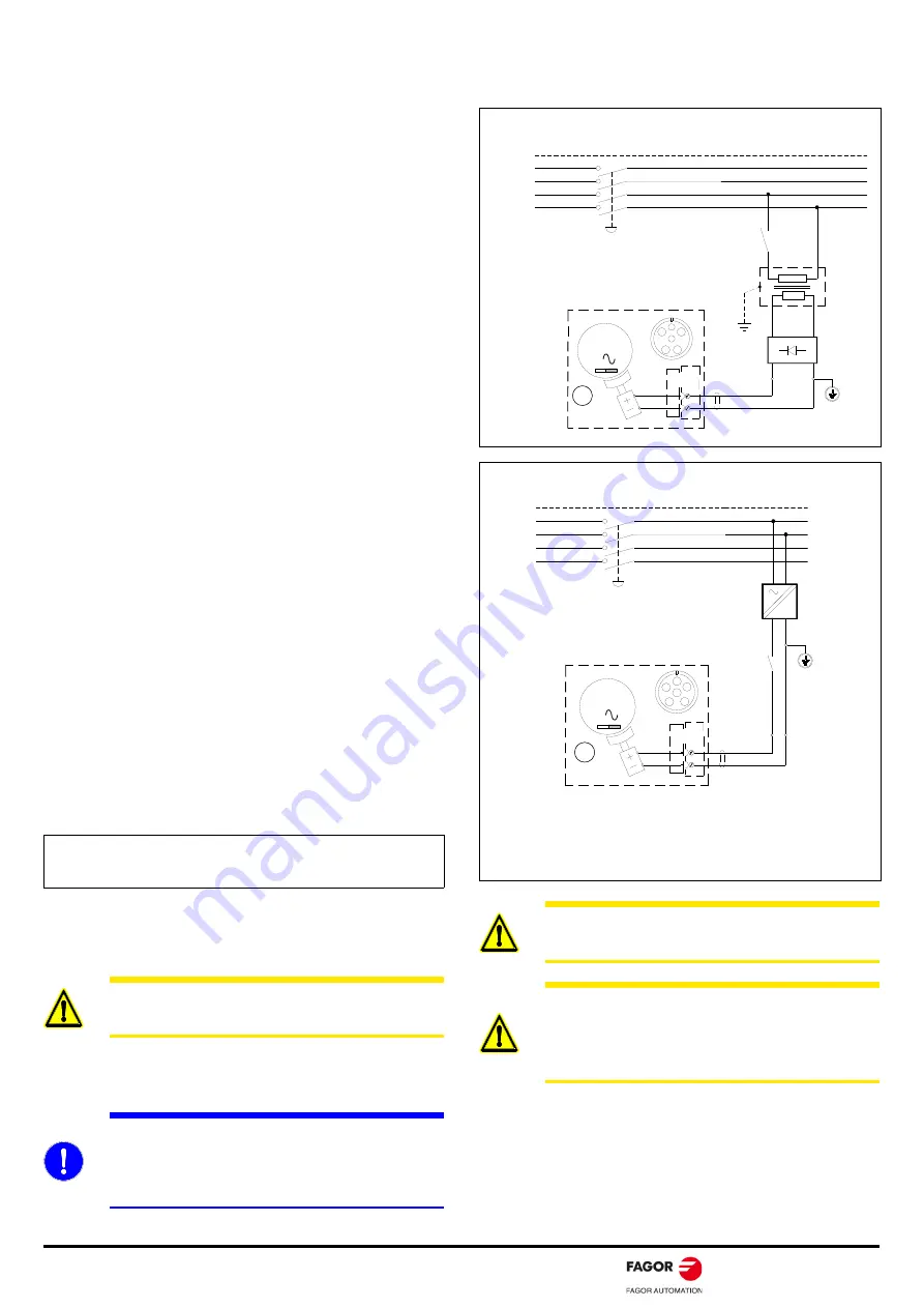
HOLDING BRAKE SUPPLY CIRCUIT
The holding brake of the FXM and FKM motors is unlocked by
applying 24 Vdc through a connector.
Note.
FAGOR does not provide exterior main or auxiliary 200/240
Vac power supplies. All these are designed to be supplied with line
voltages of between 400 (1-10 %) Vac and 460 (1+10 %) Vac.
WARNING.
This brake must never be used to brake
moving axes. It must only be used to hold or lock vertical
axes that have been stopped previously!.
MANDATORY.
While the brake is locking the vertical axis
motor, the motor must be kept with torque. See parameter
GP9. When powering the machine up, the brake must
never be released until the system assumes control of that
axis. See the TV100 variable.
WARNING.
When installing the motor, verify that the
brake releases the shaft completely before turning it for
the first time.
WARNING.
Power the holding brake of the FKM motors
with a power supply that provides a continuous, stabilized
voltage of 24 Vdc. To ensure safe operation in the event
of large temperature variations, the coil must be powered
with stabilized direct current.
PE
3x 400-460 VAC
L1
FXM MOTOR
BRAKE
E
F
+24 VDC
0 VDC
BR
24 VAC
230 VAC
E
F
3
M
Z
- S1
MECHANICAL MAIN SWITCH
SIMPLE CIRCUIT TO POWER
THE FXM MOTOR BRAKE
LINE VOLTAGE
(R)
(S)
(T)
L2
L3
N
PROTECTIVE
EARTH
NOTE. RST, Classic nomenclature; L1 L2 L3, current nomenclature
FKM MOTOR
BRAKE
4
5
+24 VDC
0 VDC
BR
3
M
Z
4
5
+24 V
=
400 VAC
0 V
PE
3x 400-460 VAC
L1
LINE VOLTAGE
(R)
(S)
(T)
L2
L3
N
- S1
MECHANICAL MAIN SWITCH
PROTECTIVE
EARTH
STABILIZED
24 V DC
POWER SUPPLY
NOTE.. RST, Classic nomenclature; L1 L2 L3, current nomenclature
WARNING. For FKM motors
Power the holding brake with a power supply that provides a continuous, stabilized voltage
of 24 Vdc. To ensure safe operation in the event of large temperature variations, the
coil must be powered with stabilized direct current.
Summary of Contents for 2104
Page 1: ...FAGOR AUTOMATION Ref 2104 Original instructions FAGOR AUTOMATION DDS Modular Quick Reference...
Page 5: ......
Page 6: ......
Page 7: ......
Page 82: ...MQR 82 84 Fagor Modular Drives and Motors Quick Reference Ref 2104 User notes...
Page 83: ...Fagor Modular Drives and Motors Quick Reference Ref 2104 MQR 83 84 User notes...


