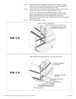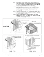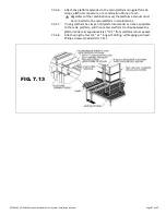
PATHWAY HD Code Compliant Modular Access System Installation Manual
Page 81 of 92
7.1.5.
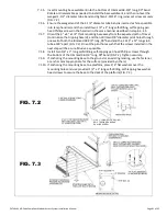
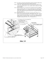
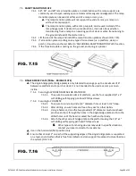
Insert mounting base weldment into the bottom of trimmed 38-3/4” long, 90
0
bend.
Rotate or disassemble as needed to install the base weldment, and then re-level the
swaged 1-1/2” diameter tube bend and tighten 2-15/16” ring joiner set screw securely
(FIG. 7.2).
7.1.6.
Ensure the swaged end of the 1-1/2” diameter tube bend is inserted as far as possible
into ramp handrail, and then install two 1/4” x 1” long self-drilling, self-tapping pan
head Phillips screws in the handrail in the same manner described in step 6.3.2.5.
7.1.7.
Orient the 4” x 4” x 1/4” thick mounting base away from the expected path of travel
(to minimize the tripping hazard), and then drill two 1/8” diameter pilot holes through
one wall of both the trimmed 38-3/4” long, 90
0
bend and the 1.315” x 12” long stub
tube at 90° apart (FIG. 7.2). Orient the pilot holes such that the screws installed in the
next step will be as unobtrusive as possible.
7.1.8.
Install two 1/4” x 1” long self-drilling, self-tapping pan head Phillips screws through
the bottom of the trimmed 38-3/4” long, 90
0
bend (FIG 7.2). Tighten securely.
7.1.9.
If anchoring the mounting base to the ground or an existing landing, use the fastener
or anchor most appropriate for the surface (provided by others).
7.1.10.
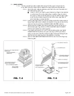
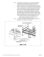
If anchoring the mounting base to a platform, place 1/4” flat washers over the
mounting holes and use provided 1/4” x 1” long self-drilling, self-tapping hex washer
head screws to secure the base to the deck of the platform (FIG. 7.3).
FIG. 7.2
FIG. 7.3
1/4” X 1” LONG SELF-DRILLING,
SELF-TAPPING PAN HEAD
PHILLIPS SCREW


