PATHWAY HD Code Compliant Modular Access System Installation Manual
Page 50 of 92
5.6.7.
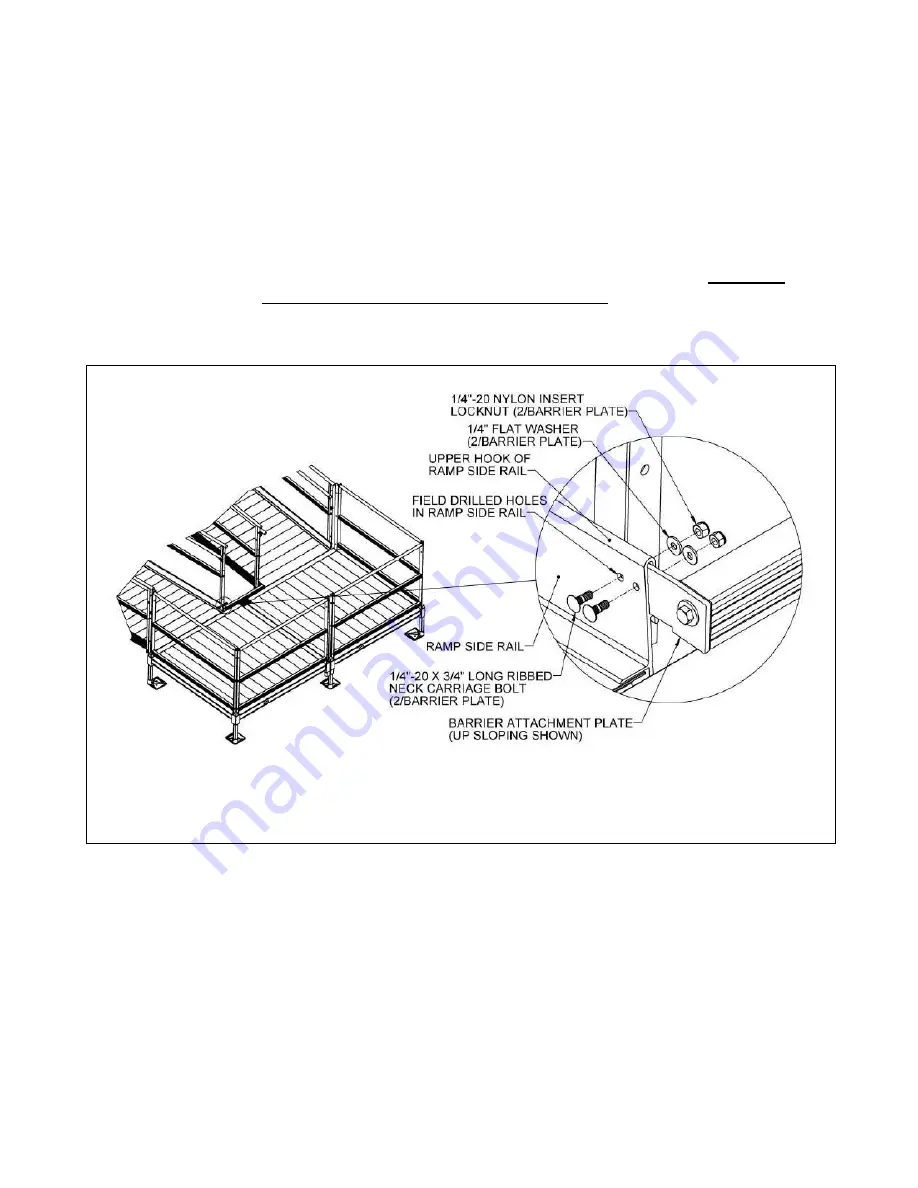
Place the assembly into the space between the ramp side rails. Make sure the legs
of the barrier attachment plates with the two smaller holes are captured under the
upper hooks and in contact with the ramp side rails. Move the ramps slightly if
needed. Level the barrier with respect to the platform and clamp the attachment
plates to the side rails, if possible, before drilling (FIG. 5.22).
5.6.8.
Use the two smaller holes in the barrier attachment plates to drill two 1/4” or
9/32” holes through each ramp side rail (FIG. 5.22).
5.6.9.
Connect the barrier attachment plates to the ramp side rails using 1/4”-20 x 3/4” long
ribbed neck carriage bolts, 1/4”-20 nylon insert locknuts, and 1/4” flat washers. Orient
the head of the carriage bolt on the ramp side as shown (FIG. 5.22).
5.6.10.
For the mid rail, first measure the distance between the frame posts at the turn
back, and then cut the 1-1/2” x 2” mid rail to the measured length less 5/8” to
account for threaded inserts and attachment plates which will be installed in the
following steps.
5.6.11.
Using a metal file, remove all sharp edges from cutting.
FIG. 5.22


