PATHWAY HD Code Compliant Modular Access System Installation Manual
Page 68 of 92
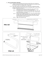
FIG. 5.47
5.10.4.
Insert a 2-15/16” ring joiner in one of the ramp
handrails at the corner turn, followed by an
adjustable elbow and another 2-15/16” ring
joiner. Orient the ring joiner set screws toward
the underside of handrail. Tighten ring joiner
set screws and adjustable elbow assembly
screw enough to hold components in place but
still allow them to rotate. Install 2-15/16” ring
joiners and adjustable elbow in the other ramp
handrail in the same manner (FIG. 5.47).
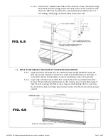
5.10.5.
Align the faces of the two closest 2-15/16” ring
joiners in the corner and measure gap between
the two parallel faces. Trim the 1-1/2” diameter
tube to measured length (FIG. 5.47).
5.10.6.
Using a metal file, remove sharp edges from
cutting.
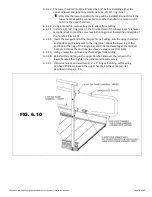
5.10.7.
Install trimmed 1-1/2” diameter tube in gap
between the 2-15/16” ring joiners. Disassemble
and reassemble ring joiners and adjustable
elbows as needed to complete the installation
(FIG. 5.48).
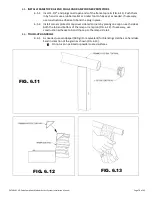
5.10.8.
Insert 1-1/2” end plugs on all open ends of
frame top rails. Use a rubber mallet or similar
tool to fully seat as needed. If necessary, use
construction adhesive to bond plug in place.
5.10.9.
Tighten all fasteners securely, including all ring
joiner set screws and elbow assembly screws if
not completed previously.
FIG. 5.48


