PATHWAY HD Code Compliant Modular Access System Installation Manual
Page 43 of 92
5.4.3.
Locate the appropriate barrier attachment plate. If the upper end of the ramp or ramp
run terminates at a platform, use the “up sloping” version of the plate. If the lower
end of a ramp or ramp run starts at a platform, use the “down sloping” version. Note
the orientation of the larger 3/8” diameter hole with respect to the 1-1/2” x 2” section
of the plate as shown (refer back to FIG. 5.3) to identify which barrier attachment
plate is needed.
5.4.4.
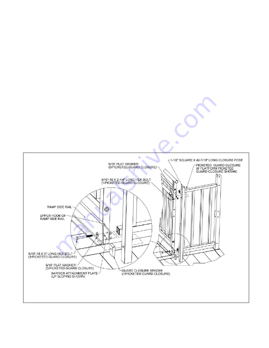
Fasten barrier attachment plate to the lowermost hole in the 1-1/2” square x 42-7/16”
long closure post and lower rail of the picketed guard closure using a 5/16”-18 x 3”
long hex bolt and 5/16” flat washer with the guard closure spacer between the barrier
attachment plate and the closure post.
5.4.4.1.
Orient the closure post with the two holes which are the closest together
on top. If the uppermost hole in the closure post does not align with the
uppermost hole in the platform angle post, the closure post is upside
down. Make sure the leg of the attachment plate with the two smaller
holes is captured under the upper hook and in contact with the ramp side
rail. Move the ramp or platform slightly (if needed) and clamp the
attachment plate to the side rail if possible before drilling (FIG. 5.14).
5.4.5.
Attach upper rail of picketed guard closure to closure
post using a 5/16″
-18 x 2-
1/4″
hex bolt and 5/16” flat washer though the second hole from the top of the closure
post (FIG. 5.14).
5.4.6.
Drill holes in the ramp side rail and attach the barrier attachment plate to the side
rail in the same manner described in ‘CLOSURES’ section and shown (refer back to
FIG. 5.5).
FIG. 5.14


