PATHWAY HD Code Compliant Modular Access System Installation Manual
Page 49 of 92
5.6.3.
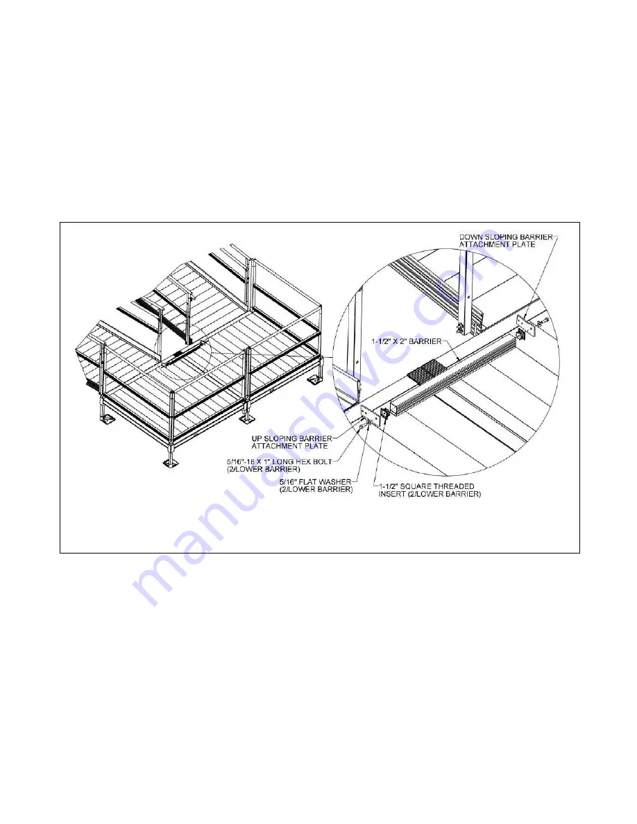
The barrier is provided in the length needed for the platform side and should not need
to be trimmed. Insert 1-1/2” square threaded inserts into both ends of the 1-1/2” x 2”
barrier. Use a rubber mallet or similar tool to fully seat as needed (FIG. 5.21).
5.6.4.
Assemble barrier attachment plates to barrier using a 5/16”-18 x 1” long hex bolts and
5/16” flat washers. Note which side of the barrier the plates are attached to and
match the direction of ramp slope. If the upper end of the ramp or ramp run
terminates at a platform, use the “up sloping” plate. If the lower end of a ramp or
ramp run starts at a platform use the “down sloping” plate.
5.6.5.
Note the orientation of the larger 3/8” diameter hole with respect to the 1-1/2” x 2”
section of the plate (refer back to FIG. 5.3) to identify which barrier attachment plate
is needed.
5.6.6.
Align the barrier attachment plates with sides of the barrier and tighten fasteners
securely (FIG. 5.21).
FIG. 5.21


