background image


7-5

Fiber Matrix 6400 Switcher • Maintenance and Modifications


100-240V      50/60H

z

1.2A MAX.

100-240V      50/60H

z

1.2A MAX.

REDUND

ANT

PRIMAR

Y

1 - 8

9 - 16

17 - 24

25 - 32

33 - 40

41 - 48

49 - 56

57 - 64

LAN

ACT

LINK

RESE

T

ANAHEIM

, CA

PRIMAR

Y PO

WER SUPPL

Y

REDUND

ANT PO

WER SUPPL

Y

OUT

IN

A

OUT

IN

B

OUT

IN

C

OUT

IN

D

OUT

IN

E

OUT

IN

F

OUT

IN

G

OUT

IN

H

OUT

IN

A

OUT

IN

B

OUT

IN

C

OUT

IN

D

OUT

IN

E

OUT

IN

F

OUT

IN

G

OUT

IN

H

OUT

IN

A

OUT

IN

B

OUT

IN

C

OUT

IN

D

OUT

IN

E

OUT

IN

F

OUT

IN

G

OUT

IN

H

OUT

IN

A

OUT

IN

B

OUT

IN

C

OUT

IN

D

OUT

IN

E

OUT

IN

F

OUT

IN

G

OUT

IN

H

OUT

IN

A

OUT

IN

B

OUT

IN

C

OUT

IN

D

OUT

IN

E

OUT

IN

F

OUT

IN

G

OUT

IN

H

OUT

IN

A

OUT

IN

B

OUT

IN

C

OUT

IN

D

OUT

IN

E

OUT

IN

F

OUT

IN

G

OUT

IN

H

OUT

IN

A

OUT

IN

B

OUT

IN

C

OUT

IN

D

OUT

IN

E

OUT

IN

F

OUT

IN

G

OUT

IN

H

Align with Plastic Guides

Knurled Knobs

Knurled Knobs

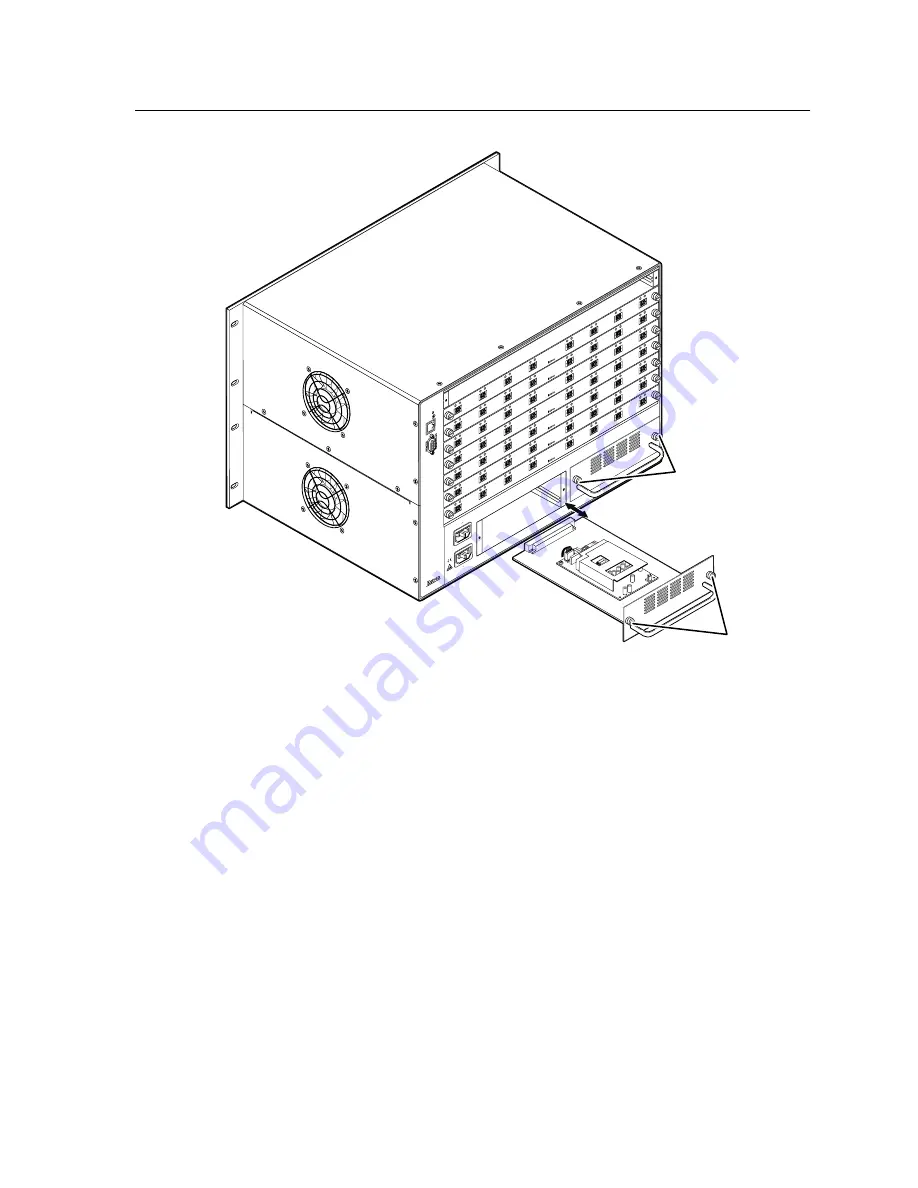
Figure 7-3 — Power supply replacement

Installing the power supply module

N

  The power supply modules are hot-swappable.  You do not need to power down 

the switcher to install a power supply.

Install a power supply module as follows:

1

Orient the power supply module to be installed with the LED to the right.

2

Align the flanges on the power supply module with the left and right power 

supply guides (figure 7-3).

3

Gently slide the power supply module into the enclosure until the power 

supply meets resistance.

4

Gently seat the power supply in the backplane.

5

Tighten the left and right knurled knobs/captive screws to lock the power 

supply in place.

N

  If necessary, use a screwdriver to tighten the knurled knobs/captive screws.

Summary of Contents for 6400s

Page 1: ...Fiber Matrix 6400 Configurable Fiber Optic Digital Matrix Switcher 68 1371 01 Rev B 06 08...

Page 2: ...m machen da im Inneren des Geh uses dieses Produktes gef hrliche Spannungen die nicht isoliert sind und die einen elektrischen Schock verursachen k nnen herrschen Achtung Lesen der Anleitungen Bevor S...

Page 3: ...ction against harmful interference when the equipment is operated in a commercial environment This equipment generates uses and can radiate radio frequency energy and if not installed and used in acco...

Page 4: ......

Page 5: ...ear Panel Cabling and Features 2 3 I O boards 2 4 Reset button and LED 2 6 Ethernet connection 2 6 Cabling 2 6 RJ 45 connector wiring 2 7 Remote port 2 8 Power 2 8 Front Panel Configuration Port 2 9 C...

Page 6: ...ion Worksheets 3 32 Worksheet example 1 System equipment 3 32 Worksheet example 2 Daily configuration 3 34 Worksheet example 3 Test configuration 3 36 Blank configuration worksheet 3 39 Chapter Four P...

Page 7: ...ton 5 11 GMT offset field 5 11 Use Daylight Savings checkbox 5 11 Administrator Password and User Password fields 5 11 Mail Server IP Address field 5 12 Mail Server Domain Name field 5 12 E mail Addre...

Page 8: ...ings fields 6 6 Passwords page 6 8 Email Settings page 6 9 Mail IP Address field 6 9 Domain Name field 6 9 Email Address fields 6 10 Firmware Upgrade page 6 10 File Management Page 6 12 Special Charac...

Page 9: ...turn line feed A 5 Close A 5 Help A 5 Quit A 5 Subnetting A Primer A 6 Gateways A 6 Local and remote devices A 6 IP addresses and octets A 6 Subnet masks and octets A 6 Determining whether devices are...

Page 10: ...Table of Contents cont d Fiber Matrix 6400 Switcher Table of Contents vi...

Page 11: ...Fiber Matrix 6400 Switcher 1 Chapter One Introduction About this Manual About the Fiber Matrix 6400 Switcher Definitions Features...

Page 12: ...T IN A OUT IN B OUT IN C OUT IN D OUT IN E OUT IN F OUT IN G OUT IN H OUT IN A OUT IN B OUT IN C OUT IN D OUT IN E OUT IN F OUT IN G OUT IN H M S M S M D M S 57 64 MUTI RATE SDI INPUTS H G A D E F C B...

Page 13: ...d the SDI HD SDI video signals on BNC connectors The matrix switcher can be remotely controlled via its rear panel RS 232 RS 422 Remote port its rear panel LAN port and its front panel Configuration R...

Page 14: ...With fiber optic I O boards the switchers input and output fiber optic signals on optical connectors The fiber optic I O boards support digital signals from 270 Mbs through 4 25 Gbps SDI HD SDI or 3G...

Page 15: ...distribution plane is separate and redundant figure 1 2 If the installation includes uninterruptible or completely separate power sources the switcher will remain powered up through any power interru...

Page 16: ...create labels to place in the front panel I O buttons with names alphanumeric characters or color bitmaps for easy and intuitive input and output selection Alternatively labels can be made with any B...

Page 17: ...Fiber Matrix 6400 Switcher 2 Chapter Two Installation Setup Installation Checklist Mounting the Switcher Rear Panel Cabling and Features Front Panel Configuration Port...

Page 18: ...the rack environment may be greater than room ambient temperature Therefore install the Fiber Matrix in an environment compatible with the maximum ambient temperature Tma 122 F 50 C specified by Extro...

Page 19: ...OUT IN D OUT IN E OUT IN F OUT IN G OUT IN H OUT IN A OUT IN B OUT IN C OUT IN D OUT IN E OUT IN F OUT IN G OUT IN H OUT IN A OUT IN B OUT IN C OUT IN D OUT IN E OUT IN F OUT IN G OUT IN H OUT IN A OU...

Page 20: ...board installed Slot 4 O 2 I 2 O 3 I 3 O 4 I 4 O 9 I 25 I 26 I 27 I 28 I 29 I 30 I 31 I 32 O 25 O 26 O 27 O 28 O 29 O 30 O 31 O 32 I 9 O 10 I 10 O 11 I 11 O 12 I 12 O 5 I 5 O 6 I 6 O 7 I 7 O 8 I 8 O...

Page 21: ...500 Tx transmitter or to any other compatible Extron FOX 500 device N Or for the FOX 500 serial return receiver to transmitter function connect the free end to the Optical 2 connector on a FOX 500 Rx...

Page 22: ...this RJ 45 connector You can use a PC to control the networked switcher with SIS commands from anywhere in the world You can also control the switcher from a PC that is running Extron s Windows based...

Page 23: ...12345678 Insert Twisted Pair Wires Pins RJ 45 connector Patch straight cable Side 1 Side 2 Pin Wire color Pin Wire color 1 White orange 1 White orange 2 Orange 2 Orange 3 White green 3 White green 4 B...

Page 24: ...S 422 serial communication protocol and can operate at 9600 19200 38400 or 115200 baud rates See Selecting the rear panel Remote port protocol and baud rate on page 3 27 to configure the RS 232 RS 422...

Page 25: ...70 335 01 figure 2 7 can be used for this connection 6 feet 1 8 m Part 70 335 01 5 1 9 6 Sleeve Gnd Ring Tip 9 pin D Connection TRS Plug Pin 2 Computer s RX line Tip Pin 3 Computer s TX line Ring Pin...

Page 26: ...tances from the matrix switcher to the controlling device can vary up to 200 feet 61 m Factors such as cable gauge baud rates environment and output levels from the switcher and the controlling device...

Page 27: ...iber Matrix 6400 Switcher 3 Chapter Three Operation Front Panel Controls and Indicators Rear Panel Power Indicators Front Panel Operations Rear Panel Operations Troubleshooting Configuration Worksheet...

Page 28: ...63 64 I N P U T S O U T P U T S 1 2 3 4 5 6 7 8 9 10 11 12 13 14 15 16 17 18 19 20 21 22 23 24 25 26 27 28 29 30 31 32 58 33 34 35 36 37 38 39 40 41 42 43 44 45 46 47 48 49 50 51 52 53 54 55 56 57 59...

Page 29: ...ink Preset location is selected to be saved Output mutes Action indication Outputs Press and hold to mute the audio or RS 232 output Outputs blink Output audio or RS 232 is muted Port configuration Ac...

Page 30: ...e Select View mode Cancel escape Indication Blink save needed Blink Save preset Lit Recall preset View mode selected Flashes once ENTER PRESET VIEW ESC Secondary functions I O Grouping Action indicati...

Page 31: ...lecting the rear panel Remote port protocol and baud rate on page 3 27 Select 19200 baud for the RS 232 RS 422 port in Serial Port Selection and Configuration mode and indicate its selection See Selec...

Page 32: ...ecutive mode on page 3 25 Power indicators g Primary and Redundant Power Supply LEDs Green Indicates that the associated power supply is operating within normal tolerances Red Indicates that the assoc...

Page 33: ...upply is operating within normal tolerances Red Indicates that the associated power supply has failed See chapter 7 Maintenance and Modifications to replace the power supply Front Panel Operations The...

Page 34: ...r as determined by the operator The switchers support up to 10 rooms each of which can consist of from 1 to 64 outputs Room memory preset A configuration consisting of outputs in a single room that ha...

Page 35: ...epeat steps 1 through 3 to create or delete additional ties until the desired configuration is complete N Only one input can be tied to an output If a tie is made between an input and an output and th...

Page 36: ...The button lights green 3 Select the outputs Press and release the output 3 output 4 and output 8 buttons C O N T R O L PRESET ENTER ESC VIEW 1 2 3 4 5 6 7 8 15 16 17 18 19 20 21 22 23 24 31 32 OUTPU...

Page 37: ...ction N This example assumes that you have performed example 1 1 Clear all selections Press and release the Esc button C O N T R O L PRESET ENTER ESC VIEW Press the Esc button to clear all selections...

Page 38: ...put 1 button The button blinks green to indicate that the selected input will be tied to this output 4 Confirm the change Press and release the Enter button ENTER All input buttons and output buttons...

Page 39: ...button 1 2 3 4 5 6 7 8 15 16 17 18 19 20 21 22 23 24 31 32 OUTPUTS 1 2 3 4 5 6 7 8 15 16 17 18 19 20 21 22 23 24 31 32 INPUTS Press and release the Input 5 button The button lights green The Output 1...

Page 40: ...video tied to outputs 1 3 and 8 Input Output 1 3 8 5 Viewing a configuration The current configuration can be viewed using the front panel buttons The View only mode prevents inadvertent changes to t...

Page 41: ...ly ends Example 4 Viewing ties In the following example the ties in the current configuration are viewed The steps show the front panel indications that result from your action N This example assumes...

Page 42: ...of ties by selecting a tied output For example note the number of a lit output button and then press and release the output button for an untied unlit or background illumination output Observe that a...

Page 43: ...55 56 57 58 59 1 2 3 4 5 6 7 8 9 10 11 17 18 19 20 21 22 23 24 25 26 27 33 34 35 36 37 38 39 40 41 42 43 49 50 51 52 53 54 55 56 57 58 59 1 2 3 4 5 6 7 8 9 10 11 17 18 19 20 21 22 23 24 25 26 27 33 34...

Page 44: ...play the ungrouped inputs and outputs 3 Press and release one of the Control buttons to select a group Press the Enter button to select group 1 Press the Preset button to select group 2 Press the View...

Page 45: ...ns The button flashes once 2 Select I O Group mode Press and hold the Input 1 and Output 1 buttons for approximately 2 seconds and then release the buttons 1 1 17 18 19 1 2 3 17 18 19 1 2 3 Press and...

Page 46: ...O L PRESET ENTER ESC VIEW Press and release the Preset button to select group 2 The button lights amber to indicate the selection 1 3 2 4 Group 6 Assign inputs and outputs Press and release the input...

Page 47: ...configuration ties Example 6 Saving a preset In the following example the current configuration is saved as a preset The steps show the front panel indications that result from your action 1 Clear al...

Page 48: ...that result from your action 1 Clear all selections Press and release the Esc button C O N T R O L PRESET ENTER ESC VIEW Press the Esc button to clear all selections The button flashes once 2 Select...

Page 49: ...d unmuting outputs Individual outputs can be muted or unmuted as follows 1 Press the Esc button to clear any front panel button indications that may be on 2 Press and release the View button 3 One at...

Page 50: ...y mode The View button lights red C O N T R O L PRESET ENTER ESC VIEW 1 2 3 4 5 6 7 8 15 16 17 18 19 20 21 22 23 24 31 32 OUTPUTS Until you select an input only the buttons for untied outputs light Pr...

Page 51: ...ground illumination VIEW Press the View button to exit View Only mode The View button returns to unlit or background illumination Locking out the front panel Executive mode The front panel security lo...

Page 52: ...2 B TX LIN K A TX LIN K 1 RX LIN K 2 B TX LIN K 1 RX LIN K 2 C TX LIN K 1 ANAHEIM CA PRIM ARY POWER SUPPLY 41 48 49 56 57 64 CONTROL T VIEW ESC Press and hold the View and Esc buttons while you apply...

Page 53: ...tocol as follows Output 63 RS 232 Output 64 RS 422 RS 485 In this example the port is set to RS 232 at 9600 baud Press and hold the Enter Preset View and Esc buttons All Control buttons light with one...

Page 54: ...he version number Use mode 1 to revert to the factory default firmware version if incompatibility issues arise with user loaded firmware 3 Hold down the Reset button for about 3 seconds until the Rese...

Page 55: ...ESC CONTROL T VIEW ESC CONTROL T VIEW ESC Release then immediately press and release again 6 seconds 9 seconds Press and hold the Reset button 3 seconds View and Esc buttons flash once Reset LED flas...

Page 56: ...1 If necessary turn off power to the switcher 2 Press and hold the Reset button on the rear panel while you apply AC power to the switcher 10 0 2 40 V 50 60 Hz 1 2 A MA X 10 0 2 40 V 50 60 Hz 1 2 A MA...

Page 57: ...in and powered on The switcher is receiving power if one of the front panel Power Supply LEDs is lit green 2 Check to see if one or more outputs are muted 3 Ensure an active input is selected for outp...

Page 58: ...r Matrix in a fictional organization with the system hardware annotated Inputs 10 11 25 30 35 40 and 45 through 48 have no connections in this organization so they have been crossed out on the workshe...

Page 59: ...Floorbox 1 2 Floorbox 2 1 Floorbox 2 4 Floorbox 2 3 Floorbox 2 2 Floorbox 3 1 Floorbox 3 4 Floorbox 3 3 Floorbox 3 2 Floorbox 5 1 Floorbox 5 4 Floorbox 5 3 Floorbox 5 2 Floorbox 4 1 Floorbox 4 4 Floo...

Page 60: ...yed in the main hall output 1 Displayed in the conference room output 4 to the overflow crowd Displayed in the lobby output 8 Tied to the VCR output 6 The presenter has a presentation on her laptop co...

Page 61: ...Camera 2 Floorbox 1 1 Floorbox 1 4 Floorbox 1 3 Floorbox 1 2 Floorbox 2 1 Floorbox 2 4 Floorbox 2 3 Floorbox 2 2 Floorbox 3 1 Floorbox 3 4 Floorbox 3 3 Floorbox 3 2 Floorbox 5 1 Floorbox 5 4 Floorbox...

Page 62: ...ation needs to be fine tuned on a regular basis Figure 3 7 shows a typical test configuration with an Extron video test generator input 12 generating a test pattern to all monitors outputs 1 2 3 4 8 9...

Page 63: ...Camera 2 Floorbox 1 1 Floorbox 1 4 Floorbox 1 3 Floorbox 1 2 Floorbox 2 1 Floorbox 2 4 Floorbox 2 3 Floorbox 2 2 Floorbox 3 1 Floorbox 3 4 Floorbox 3 3 Floorbox 3 2 Floorbox 5 1 Floorbox 5 4 Floorbox...

Page 64: ...Operation cont d Fiber Matrix 6400 Switcher Operation 3 38...

Page 65: ...3 24 25 10 11 12 13 14 15 16 1 2 3 4 5 6 7 8 9 58 59 60 61 62 63 64 49 50 51 52 53 54 55 56 57 42 43 44 45 46 47 48 33 34 35 36 37 38 39 40 41 26 27 28 29 30 31 32 17 18 19 20 21 22 23 24 25 10 11 12...

Page 66: ...Operation cont d Fiber Matrix 6400 Switcher Operation 3 40...

Page 67: ...de Serial Ports Ethernet Port Host to Switcher Instructions Switcher Initiated Messages Switcher Error Responses Using the Command Response Tables Command Response Table for SIS Commands Command Respo...

Page 68: ...no flow control The ports can be configured to operate at the 9600 19200 38400 or 115200 baud rate N These two ports are independent of one another A front panel Configuration port connection and a r...

Page 69: ...via an SIS command only See the Command Response table for IP Specific SIS commands later in this chapter to configure both ports using an SIS command The optional 9 pin D to 2 5 mm mini jack TRS RS...

Page 70: ...t through cable or a crossover cable and must be properly terminated for your application figure 4 1 Crossover cable Direct connection between the computer and the Fiber Matrix switcher Patch straight...

Page 71: ...s the copyright message N If the switcher is password protected a password prompt appears below the copyright message 2 If the switcher is password protected enter the appropriate administrator or use...

Page 72: ...below underlined c Copyright 2007 Extron Electronics Fiber Matrix 6400 Vx xx 60 878 01 day date time The switcher initiates the copyright message when it is first powered on or when connection via In...

Page 73: ...response to the host The error response codes are E01 Invalid input channel number too large E10 Invalid command E11 Invalid preset number E12 Invalid output number too large E13 Invalid value out of...

Page 74: ...m for input names output names global preset names and room preset names 11 characters maximum for room names Upper and lower case alphanumeric characters and _ and spaces are valid N The following ch...

Page 75: ...e E QX X X X Qik Example E Q3 4 3 5 3 6 Qik Tie input 3 to output 4 tie input 3 to output 5 and tie input 3 to output 6 Tie input to all outputs X InX All Example 5 In05 All Tie input 5 to all outputs...

Page 76: ...I See below 01 Input Gri Response s group Input 1 in group 4 02 03 04 05 06 07 08 09 10 15 16 4 0 1 3 3 0 0 0 0 4 4 4 11 12 13 14 0 0 0 4 Input 2 not grouped Input 16 in group 4 Input 1 Group 4 Input...

Page 77: ...ins unchanged unless overwritten or cleared If you do not clear the ties in a global preset number before you directly write a global preset to that number ties that are part of the previous version o...

Page 78: ...l valid and equivalent RmmX SprX Example 7 3P12 7 11 5 4 5 6 6 Esc Brackets are shown to separate ties for clarity only Create preset 3 for room 7 which ties input 12 to output 7 input 11 to output 5...

Page 79: ...6 No inputs are tied to outputs 7 and 8 N EX 1 1VC where X 0 returns the switcher s current video configuration View room preset configuration EX X X 1VC X n X n 1 X n 15 Vid Show room X preset X1 s c...

Page 80: ...preset is unassigned the X1 displays unassigned If a global preset is saved but not yet named the default name is Preset X If a room preset is saved but not yet named the default name is RmX PrstX Wr...

Page 81: ...g for this product SX1 1X1 2 X1 8 shows the board type installed in each slot Slot plane LC information 0 X1 I X1 aX1 bX1 cX1 dX1 eX1 fX1 gX1 h Request part number N 60 878 01 See appendix A for part...

Page 82: ...X2 Response description 3 3V 5V 2 5V 1 2V 12V backplane 12V redundant supply 12V primary supply Temp Fan1 RPM Fan2 RPM Example S 3 27 4 95 2 48 1 22 12 00 12 06 12 12 080 60 03013 02860 Backplane rec...

Page 83: ...apply for example xxx com N The following characters are invalid in a domain name space and The character is acceptable only as the lead in to the domain name such as extron com X4 E mail account 65...

Page 84: ...IP address ECI X3 Read hardware address ECH X3 Read of open connections ECC X3 Set subnet mask EX3 CS IpsX3 Read subnet mask ECS X3 Set gateway IP address EX3 CG IpgX3 Read gateway IP address ECG X3 S...

Page 85: ...et DHCP on or off EX4 DH IdhX4 X4 0 off 1 on Read DHCP on off status EDH X4 Set serial port parameters EX4 X4 X4 X5 X5 CP CpnX4 CcpX4 X4 X5 X5 Read serial port parameters EX4 CP X4 X4 X5 X5 Set serial...

Page 86: ...Programmer s Guide cont d Fiber Matrix 6400 Switcher Programmer s Guide 4 20...

Page 87: ...Fiber Matrix 6400 Switcher 5 Chapter Five Matrix Software Matrix Switchers Control Program Button Label Generator Program...

Page 88: ...site www extron com Installing the software The program is contained on the Extron Software Products CD ROM Install the software as follows N For full functionality install both of the following prog...

Page 89: ...age 4 19 to configure either port using an SIS command Software operation via Ethernet When a matrix switcher is connected to an Ethernet WAN or LAN up to 200 users can operate it locally or remotely...

Page 90: ...ort Selection window figure 5 3 appears Figure 5 3 Comm port selection window 2 Choose either the comm port that is connected to one of the switcher s serial ports IP LAN or Emulate If you selected a...

Page 91: ...t changed the value the factory specified default 192 168 254 254 is the correct value for this field b If the switcher is password protected click in the Password field and enter the enter the approp...

Page 92: ...Matrix Software cont d Fiber Matrix 6400 Switcher Matrix Software 5 6 Figure 5 5 Extron Matrix Switchers Control Program window blank...

Page 93: ...box that represents an input or output and drag the desired icon onto the box from the icon palette that appears For quick display of information on a specific input or output device position the poin...

Page 94: ...nistrator s password to qualified and knowledgeable personnel only N When the control program is connected to the switcher via the RS 232 link the Administrator and User Password fields are not masked...

Page 95: ...ailed or repaired status This descriptor can be changed to any valid name up to 24 alphanumeric characters N The following characters are invalid in the Extron Name Descriptor field space and Edit thi...

Page 96: ...use DHCP Date field The Date field displays the current date in the Greenwich Mean Time GMT zone If necessary adjust the date as follows 1 Click in the Date field A Set Date field appears with the dat...

Page 97: ...t its time reference Administrator Password and User Password fields The Administrator Password field displays the password required to log on to the matrix switcher via the Ethernet port with all of...

Page 98: ...server IP address field 4 Click the Take button to make the address change take effect Mail Server Domain Name field The Mail Server Domain Name field displays the domain name that the matrix switche...

Page 99: ...lick in the desired E mail Addressee field The pointer tool becomes a text cursor 2 Edit the e mail address as desired Standard e mail address conventions apply for example nnnnn xxx com 3 Press the T...

Page 100: ...le selected and shown is Fiber Matrix 6400 NOTE 1 Figure 5 8 Location of firmware upgrade files 2 Select the appropriate firmware file Fiber Matrix 6400 to download and click Download 3 Enter the requ...

Page 101: ...atrix Software 6 4 5 4 Folder where firmware is installed This sequence is shown for example only For the Fiber Matrix 6400 the firmware file selected and shown is Fiber Matrix 6400 NOTE Figure 5 9 Do...

Page 102: ...ad on the next page Ethernet connected firmware upload 11 This screen is shown for example only For the Fiber Matrix 6400 the firmware file selected and shown is Fiber Matrix 6400 NOTE Figure 5 10 Sel...

Page 103: ...d shown is Fiber Matrix 6400 NOTE Figure 5 11 Firmware loading 10 Click Browse The open file window appears 11 Navigate to the folder where you saved the firmware upgrade file Select the file and clic...

Page 104: ...the firmware file selected and shown is Fiber Matrix 6400 NOTE Figure 5 12 Confirm window 13 If necessary change the port number in the device port field Rear panel RS 232 RS 422 port enter 1 Front pa...

Page 105: ...he PC to the matrix switcher via the switcher s RS 232 RS 422 port or Ethernet port 2 Start the Matrix Switchers Control Program and connect to the Fiber Matrix switcher See Using the Matrix Switcher...

Page 106: ...the window and either activate it Go or delete it Delete Go Activates the selected preset as the current configuration Save as Allows the current set of ties to be saved as a preset Enter the preset...

Page 107: ...Displays the Input Detection screen which shows the data rates for SDI HD SDI inputs only Update Firmware Allows you to replace the firmware that is coded on the switcher s control board without taki...

Page 108: ...to 12 upper and lower case alphanumeric characters space and the _ and characters N The following characters are invalid in preset names and Show RS 232 Strings Displays the ASCII commands that are us...

Page 109: ...he Take button are indicated by Figure 5 16 Ties shown as crosspoints Link detection options Allows you to set the link detection feature as follows To automatically refresh the display every 10 secon...

Page 110: ...ation about program features you can access the help program in any of the following ways From the Extron Electronics program folder or group double click on the MATRIX Switcher Help icon shown at rig...

Page 111: ...tart Programs Extron Electronics Button Label Generator Button Label Generator The Button Label Generator window appears figure 5 18 Figure 5 18 Extron s Button Label Generator window 2 In the Systems...

Page 112: ...Matrix Software cont d Fiber Matrix 6400 Switcher Matrix Software 5 26...

Page 113: ...Fiber Matrix 6400 Switcher 6 Chapter Six HTML Operation Opening the Switcher s Embedded Web Pages System Status Page System Settings Page File Management Page Special Characters...

Page 114: ...ld 3 Enter the Matrix IP address in the browser s Address field N If the local system administrators have not changed the value the factory specified default 192 168 254 254 is the correct value for t...

Page 115: ...nstalled default startup page nortxe_index html figure 6 2 also known as the System Status page System Status Page The System Status page figure 6 2 provides an overall view of the status of the matri...

Page 116: ...the Input Link page figure 6 3 Click the Input Link link to the left of the Status page to download the Input Link page The Input Link page automatically updates itself every 30 seconds to show the l...

Page 117: ...s create and recall presets set output mutes and view all settings with the exception of passwords IP Settings fields The IP Settings fields provide a location for viewing and editing settings unique...

Page 118: ...the mail server to be used if the switcher and the mail server are not on the same subnet Standard IP protocol rules apply to the Gateway IP address Subnet Mask field The Subnet Mask field is used to...

Page 119: ...me GMT N The Zone field identifies the standard time zone selected and displays the amount of time in hours and minutes that the local time varies from the GMT international time reference 4 Repeat st...

Page 120: ...e alphanumeric characters Each password must be entered twice once in the Password field and then again in the Re enter Password field Characters in these fields are masked by asterisks If you do not...

Page 121: ...utton changes to Save After editing the associated settings with click the Save button Select Passwords Select Firmware Upgrade Refresh Select System Settings Figure 6 7 Email Settings page Mail IP Ad...

Page 122: ...e mailed of failures fixes both not notified or to be removed from the e mail list The Suspend option is useful for temporarily removing personnel from the e mail list when they are unavailable such a...

Page 123: ...10 7 9 This screen is shown for example only For the Fiber Matrix 6400 the firmware file selected and shown is Fiber Matrix 6400 NOTE Figure 6 9 Firmware upgrade 7 Click the Browse button A Choose Fil...

Page 124: ...a file Upload your own files as follows N The following characters are invalid in file names space and 1 Click the Browse button 2 Browse through your system and select the desired file s N If you wan...

Page 125: ...Matrix 6400 Switcher 7 Chapter Seven Maintenance and Modifications Removing and Installing the I O Board or Blank Panel Removing and Installing the Power Supply Module Removing and Installing Button L...

Page 126: ...panels should be installed in all locations during normal switcher operations Circuit boards can be replaced for fault correction or to accommodate SDI HD SDI electric signals They can be added or rem...

Page 127: ...damage circuits even if you cannot feel see or hear it 5 Place the removed board on an anti static surface or in an anti static container 10 0 2 40 V 50 60 Hz 1 2 A MA X 10 0 2 40 V 50 60 Hz 1 2 A MA...

Page 128: ...ard the front panel until it meets resistance 4 Gently seat the board or panel in the backplane 5 Tighten the left and right knurled knobs captive screws to lock the board or panel in place N If neces...

Page 129: ...U T IN D OU T IN E OU T IN F OU T IN G OU T IN H OU T IN A OU T IN B OU T IN C OU T IN D OU T IN E OU T IN F OU T IN G OU T IN H Align with Plastic Guides Knurled Knobs Knurled Knobs Figure 7 3 Power...

Page 130: ...t the corner Pry the two pieces apart Diffuser Base Button Label Clear Lens Figure 7 4 Illuminated button label replacement 2 Locate the notch in the corner of one side of the clear button cap lens 3...

Page 131: ...7 7 Fiber Matrix 6400 Switcher Maintenance and Modifications Button label blanks...

Page 132: ...Maintenance and Modifications cont d Fiber Matrix 6400 Switcher Maintenance and Modifications 7 8...

Page 133: ...Fiber Matrix 6400 Switcher A Appendix A Ethernet Connection Ethernet Link Subnetting A Primer...

Page 134: ...Pin Wire color Pin Wire color 1 White orange 1 White orange 2 Orange 2 Orange 3 White green 3 White green 4 Blue 4 Blue 5 White blue 5 White blue 6 Green 6 Green 7 White brown 7 White brown 8 Brown 8...

Page 135: ...4 254 bytes 32 time 10ms TTL 128 Reply from 192 168 254 254 bytes 32 time 10ms TTL 128 Ping statistics for 192 168 254 254 Packets Sent 4 Received 4 Lost 0 0 loss Approximate round trip times in milli...

Page 136: ...prompt 2 If necessary at the password prompt type password and then press Enter Connection to the switcher via the Ethernet can be password protected There are two levels of password protection admini...

Page 137: ...l echo by typing unset local_echo and then pressing Enter at the Telnet prompt If you are connected to the Fiber Matrix switcher and need to access the Telnet prompt to turn local echo off type the Es...

Page 138: ...the Fiber Matrix see IP Settings Options window in chapter 5 Matrix Software and Email Settings page in chapter 6 HTML Operation When you are setting up the variables for e mail notification which may...

Page 139: ...ontains the value 0 the related octets of the local device s and remote device s IP addresses are masked Masked octets are not compared indicated by X in the figure below If the unmasked octets of the...

Page 140: ...Ethernet Connection cont d Fiber Matrix 6400 Switcher Ethernet Connection A 8...

Page 141: ...Fiber Matrix 6400 Switcher B Appendix B Specifications Part Numbers Accessories Specifications Part Numbers and Accessories...

Page 142: ...on factors such as fiber type fiber bandwidth connector splicing losses modal or chromatic dispersion environmental factors and kinks Nominal peak wavelength 850 nm for multimode MM 1310 nm for singl...

Page 143: ...able graphic card and display used in the system Digital video output 3G HD SDI I O board multi rate SDI Number signal type 8 single link SDI HD SDI or 3Gbps HD SDI Connectors 8 female BNC Nominal lev...

Page 144: ...d 10 watts at 115 VAC 60 Hz A redundant power supply is standard Temperature humidity Storage 40 to 158 F 40 to 70 C 10 to 90 noncondensing Operating 32 to 122 F 0 to 50 C 10 to 90 noncondensing Cooli...

Page 145: ...8x8 I O board 70 650 01 Included parts These items are included in each order for a Fiber Matrix switcher Included parts Part number IEC power cords 2 Rubber feet Fiber Matrix User s Manual Extron Sof...

Page 146: ...separately Accessory Part number MKP 1000 remote keypad Black 60 239 02 White 60 239 03 RAL9010 white 60 239 05 WT water tight black 60 239 52 WT water tight white 60 239 53 MCP 1000M master 60 298 0...

Page 147: ...misuse improper handling care electrical or mechanical abuse abnormal operating conditions or non Extron authorized modification to the product If it has been determined that the product is defective...

Page 148: ...The Netherlands 800 3987 6673 31 33 453 4040 FAX 31 33 453 4050 Extron Electronics Japan Kyodo Building 16 Ichibancho Chiyoda ku Tokyo 102 0082 Japan 81 3 3511 7655 FAX 81 3 3511 7656 Extron Electron...

Reviews: