Maintenance
OTDR
273
Verifying Your OTDR
To measure the event and attenuation dead zones:
1.
Connect 2 km of fiber directly to the OTDR port. Use the shortest pulse
width and distance range possible.
³
Ensure that the OTDR port and connectors are correctly cleaned.
³
Ensure that the fiber settings are accurate (IOR, Helix factor,
and RBS).
2.
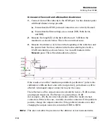
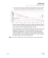
Measure the length (E) of the first reflection at 1.5 dB from the
maximum, as shown below. This is the event dead zone.
3.
Measure the distance (A) between the beginning of the reflection and
the point where the trace returns to the backscattering level with a
0.5 dB uncertainty, as shown below. Use A and B markers in the
Measure
pane. This is the attenuation dead zone.
If the results exceed the “maximum permitted specification” (refer to the
calibration certificate that came with your product), performance will be
affected. A damaged output connector may be the cause.
The reflectance of the output connector should be below –35 dB to attain
an adequate dead zone. If reflectance is greater than –35 dB
(for example, –20), the incorrect dead zone will be the result of a bad
connection. If this is the case, carefully clean the connector. If the problem
persists, change the output connector. If the problem remains even after
changing the output connector, return the OTDR to EXFO.
Note:
This does not affect the precision of the distance or loss measurements.
1.5 dB
0.5 dB
E
A

