Configure and Test Hoist Operation
28
Set and Test your Limits
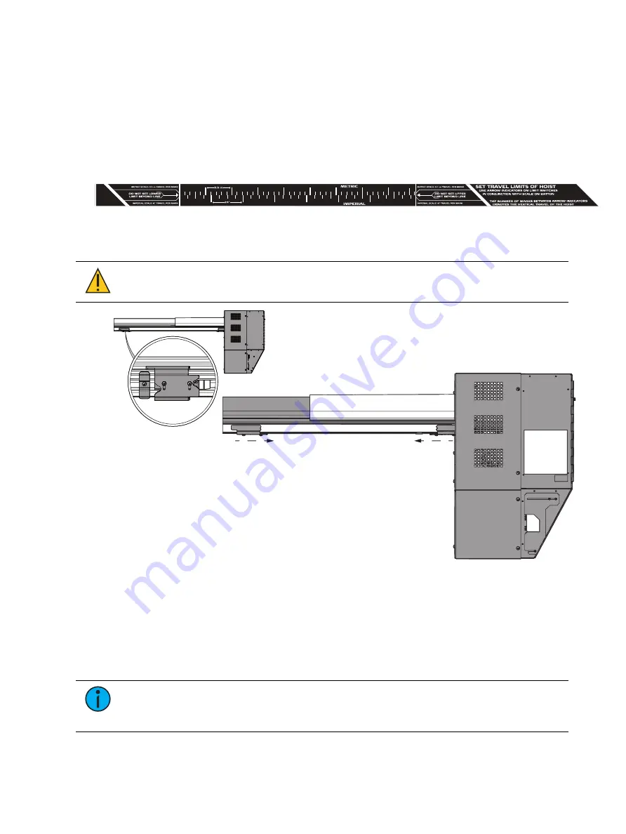
The limit switches are located in the channel on the bottom of the pipe extrusion near the motor
box. The lower limit switch is set at the lowest point of supported travel and is located closer to
the motor. The upper limit switch is set at the highest point of supported travel and rests
adjacent to a mechanical stop. This stop provides a secondary method of ensuring that the hoist
does not move beyond the uppermost point of supported travel.
There is a label on the pipe by the limit switches that provides an adjustment scale to help you
determine where to position your sleds. The following image is a truncated version of the label.
This label contains a ruler of approximate metric and imperial measurements that coincide to
feet of travel. You can use these measurements to roughly identify where you should be
positioning the limit switches. Please refer to the label for additional information.
CAUTION:
Do not loosen or move the mechanical stop that is positioned
adjacent to the upper limit switch.
Set upper limit
Set lower limit
To Set and Test the Lower Limits
1. Loosen the two Phillips screws on the bottom of the lower limit switch (closest to the
motor) and move it to the approximate position you want.
2. Tighten the screws so the switch is stationary.
3. Press the Control switch in the DOWN direction until the hoist reaches the lower hard limit
(Lower Limit status LED illuminates green).
4. Press the Control switch in the UP direction so the hoist moves off the lower hard limit.
Note:
It is important to return the batten to its normal operating range before testing
the overtravel limit. Testing the overtravel limit with full momentum of the hoist is the
desired outcome of returning the hoist to its normal operating range.


