6
6. Starting up quickly
After working through this you will be able to carry out a quick
test of your ECoS command station and to do the „first laps”
with one locomotive.
Please read the entire manual before you wire your ECoS per-
manently to your layout.
6.1. Overview of possible connections
All sockets are located at the back of your ECoS command
station:
Power:
Socket for power supply of ECoS and your lay-
out. Connect this socket only with the power
supply delivered with ECoS.
Prog-Track:
Two-way socket (5.08mm contact spacing) for
programming track (optional)
Main-Track:
Two-way socket (5.08mm contact spacing) for
mainline
AUX:
Socket for future extensions. Currently not in
use.
ECoSlink:
Three seven-way Mini-DIN sockets for di-
rect connection of external ECoSlink devices
(handheld controllers, boosters, feedback de-
coders, etc.)
ECoSlink Extend: Nine-way mini-sockets (DIN) for wiring bus-
extension modules to ECoSlink (up to 100m
total length)
Network:
10MBit Ethernet RJ45 socket for connecting
ECoS to a computer network
s88:
Six-way pin-connector for wiring Märklin®
s88-compatible feedback decoders (up to 32
modules)
ECoSniffer:
Two-way socket (3.5mm contact spacing) for
connecting existing digital systems. Wire the
track terminals of your „old” command stati-
on to this socket.
Booster:
Five-way socket (3.5mm contact spacing)
for wiring external boosters compatible with
DCC-standards or Märklin® 6017.
Starting up quickly
6.2. Minimal wiring for an initial test
• Connect the power supply to the appropriate socket of ECoS.
• Wire the two terminals „Main” to your test track.
With DCC-systems polarity is not an issue.
If you use three-rail-tracks you must observe the correct pola-
rity (“B”, “0”); otherwise many older locomotives and acces-
sories (e.g.: k83, k84) may not function properly.
Figure 4
B 0
To the
power
supply
B 0
2-digit
track
3-digit
track
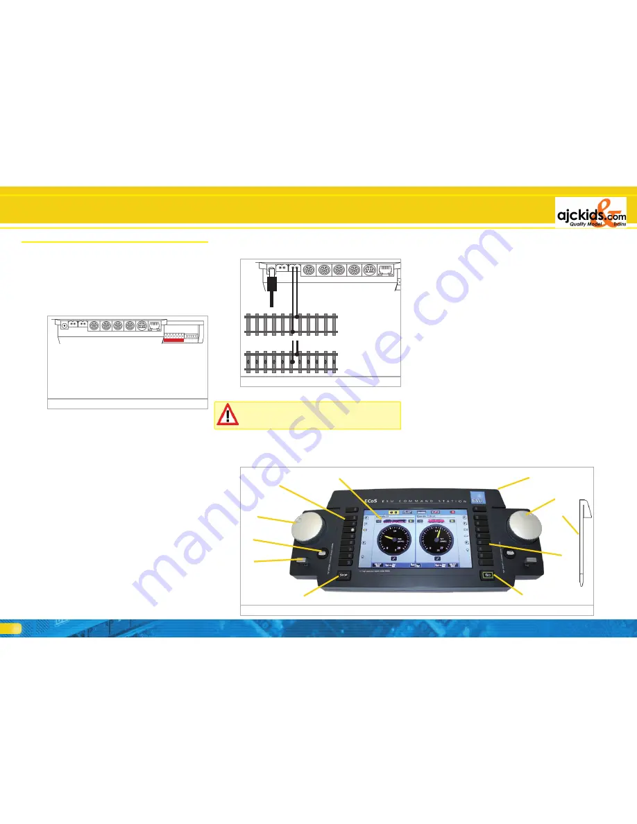
6.3. Overview of control input elements
All control input elements of ECoS are located on the top of
the housing as per Figure 5 below.
a) Function buttons on the left. The headlight function as well
as F1 to F8 of each locomotive may be activated directly
by pressing these buttons. An integral LED in the buttons
displays their status.
b) Left throttle knob with definitive end position and change-
of-direction function. Turning the knob clockwise increases
the speed while turning anti-clockwise reduces the speed..
The position of the knob corresponds with the speed. Tur-
ning the throttle knob to the left beyond the „Zero”-positi-
on to a clearly audible and mechanical „click” changes the
direction of travel.
c) Four-way joystick with centre-click-function serves for navi-
gating in the menues, selecting locomotives and to trigger
the whistle („Playable Whistle“) of locomotives equipped
with suitable decoders.
d) “Stop” button: immediately turns off the track power. Also
serves for turning off the ECoS at the end of operations
(more on this in chapter 9.2).
e) “Go” button: turns on the track power of the command
station: power is available at the track terminals.
f) Function buttons. The first 8 functions of each locomotive
can be directly activated by pushing one of these buttons.
g) Throttle (right hand side) with limit stop and change-of-
direction function.
h) Storage space for stylus.
i) Touch-sensitive touch screen with LCD display.
j) Stylus
k) Locomotive selection button. Calls up the locomotive menu
for the respective cab.
Figure 5
Figure 3
s88
ECoSnif
fer
Booster
Network
ECoSLink Extend
ECoSLink Connect
ECoSLink Connect
ECoSLink Connect
Main-T
rack
Pr
og-T
rack
Power
AUX
b)
a)
c)
d)
e)
f)
g)
h)
i)
j)
k)


