16
10.3.5. Help
i) Help menu: Context sensitive help directly on the screen
makes getting to know your ECoS very easy and gets you
out of trouble should get stuck.
10.3.6. Status line
k) Status line: Here any faults or other remarks will be dis-
played:
Low Batt:
No batteries inserted or voltage is too low.
Shut down your command station as descri-
bed in chapter 9.2 by using the “Stop” button
and replace the batteries with new ones.
Emergency stop: Track voltage is switched off manually, “Stop“
button lights up in red.
Short circuit:
The track voltage has been switched off due
to a short circuit or overload, the “Stop“ but-
ton lights up in red.
Update:
An internal software update is under way.
Operations can only continue once the up-
date has been completed. Under certain cir-
cumstances this could take up to 10 minutes.
10.4. Switch buttons
Switch buttons („fields“) serve to confirm certain actions. You
may activate them with your finger or the stylus.
This button confirms an action. Changes will be accepted and
saved.
This button cancels an action. Changes will not be saved.
10.5. Data entry fields
This symbol opens the virtual keyboard for entering text. The
current text is displayed in a data entry field.
For entering or editing text first select the choice field resul-
ting in the display of a cursor at the end of the line. Now you
can enter text and / or numbers with the aid of the displayed
keyboard.
Deletes the last character
Deletes all lines
If several fields exist, only the one that has been activated by
touching it is active. You recognise this by the frame (interrup-
ted line) around the text.
10.6. Choice lists
Choice lists allow you to select something out of a list of pos-
sible options.
Opens a list with possible options.
Confirm the desired option with your finger or the stylus.
Figure 33
10.7. Slide controller
Slide controllers make it easy to set numerical values.
Increases the current value (alternately: move joystick up-
wards)
Reduces the current value (alternatively: move joystick down-
wards)
10.8. Radio buttons and choice fields
Radio buttons enable you to make a choice out of a group of
possibilities. Only one entry can be active at any given time
similar to the pre-selection buttons of a radio tuner.
Choice fields serve for confirmation of options in ECoS. A tick
shows an active option.
Introduction to operations
top to bottom: At the top is the lighting button (F0) followed
by F1 through F8. These buttons control the functions of the
locomotive currently controlled by this cab. The integral LED of
each button indicates the current status.
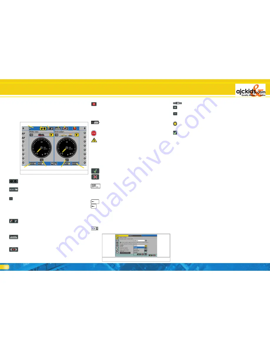
10.3. Main menue - Display mode
At the top of the main menu you can see four fields. You can
directly touch them in order to select the desired display:
10.3.1. Operational mode (running locomotives)
a) In this mode you have access to locomotive control. Each
cab can either run one locomotive (full screen display) or 5
locomotives (multi cab display).
b) Selecting a locomotive on the left: opens the locomotive
selection window for the left cab. Alternately you can press
the left locomotive selection button.
c) Locomotive menu left: opens the menu for changing set-
tings of the locomotive currently assigned to the left cab.
d) Selecting a locomotive on the right: as described in b), for
the right hand cab
e) Locomotive menu right: as described in c), for the right
hand cab
10.3.2. Turnout control panels
f) Turnout control panel: touching the appropriate symbol
calls up the turnout control panel for controlling accesso-
ries. You may continue to run your locomotives while the
turnout control panel is active.
10.3.3. Turnout control panels and track diagrams
g) Turnout control panels and track diagrams: In this mode
you can switch accessories and routes on several panels cor-
responding to the real layout track configuration.
10.3.4. Set-up
h) Set-up menu: this opens the general set-up menu. Here
you can adjust all general settings such as brightness and
contrast of the screen or “Out-and-back” operations. You
can also configure your ECoSlink devices and the booster
current threshold.
Figure 32
a)
f)
g)
h)
i)
c)
b)
e)
d)
k)


