28
16.1.6. Mirroring turnouts
In order to draw so called 45º yard ladders it may be necessary
to mirror turnouts. Thus a right hand turnout changes to be a
left hand one. Only right hand and left hand turnouts can be
mirrored.
• Select the screen button “Mirror turnout”.
• Click onto the symbol of the (right hand or left hand) turnout
that you wish to mirror.
16.1.7. Delete symbols
Symbols no longer required or inserted by mistake can be de-
leted at any time.
Only the track and accessory symbols are deleted not the actual
accessories or routes. If you wish to delete an accessory or rou-
te you must do this in the turnout control panel.
• Select the screen button “Delete symbol.
• Click onto the symbol that you wish to delete.
16.1.8. Change the name of the page
While in the configuration mode you may give each page (pa-
nel) its own name.
• Select the panel whose name you want to change.
• Click onto the keyboard symbol and enter the name.
16.1.9. Information regarding accessories / routes
Occasionally one wants to find out which accessories or routes
are hidden behind a certain symbol. This can be done easily.
• Select the screen button “Field info“.
• Click onto the symbol of which you want more info. A window
providing detailed information will open.
Track Diagram Switching Panel & „Shuttle Train” Mode
17. Running trains in „shuttle train” mode
The shuttle train function is quite a useful tool for running loco-
motives automatically between two points (terminal stations).
ECoS differentiates between two terms:
• Shuttle train line: the track section on which the loco should
travel forward and backwards
• Loco in shuttle train mode: loco that is dynamically assigned to
a shuttle train line and travels „out and back”.
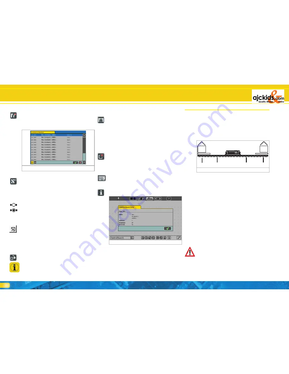
A shuttle train line must comprise of the following:
a) Station1
b) Brake point for station1
c) Station 2
d) Brake point for station 2
The train stops at each station for a pre-determined layover
time before it travels back to the other station. The sequence
happens as follows:
• As soon as the train from station 1 reaches the brake point for
station 2, ECoS transmits a „Stop” command (speed step „0”)
to the train. At the same time a timer is started inside ECoS.
• The train slows down with the set deceleration and stops. De-
celeration has to be set in such a way that the train definitely
stops in station 2. You may have to experiment a little.
• Once the pre-set layover time is past (T1), the timer gives the
signal and the train receives a command to change direction.
The train is still stopped in station 2; it is now ready for depar-
ture and the headlights are switched correctly for the return
trip.
• Once the timer signals departure time (T2) the train accelerates
and moves towards station 1. Thus the procedure begins once
again.
• The periods T1 and T2 are of equal duration. The time the train
takes from brake point 1 plus the time the train is stopped
while still set to the original direction is the same as the time
the train waits in the station after having changed the direction
setting.
• These periods are identical for both stations. The distance from
the brake points to the station must be the same in both sta-
tions since the braking distance is subject to the set decelerati-
on of the locomotive.
For detecting the brake points you have to install and assign
two s88-contacts.
Figure 78
a)
c)
b)
d)
Figure 77
• Select the screen button “Insert accessory”.
• Click onto the location in the track diagram where you want to
place the accessory.
• A window showing all accessories will open.
• Select the desired accessory.
16.1.3. Insert a route
• Select the screen button “Insert a route”.
• Click onto the location in the track diagram where you want
to place the route button. A window showing all routes will
open.
• Select the desired route.
You can switch a route in the track diagram at any time. The
currently set route is highlighted.
Route, not set
Route, all accessories set correctly
16.1.4. References to other panels
For easier navigation between different panels you can enter
references on each page. When pressing the reference symbol
that panel will be automatically displayed.
• Select the screen button “Reference to other panels”.
• Click onto the location in the track diagram where you want to
place the reference button. A window showing all panels will
open.
• Select the desired panel.
16.1.5. Turn elements
In order to achieve the desired orientation of a symbol you can
turn them clockwise, even at a later stage.
• Select the screen button “Turn symbol“.
• Click onto the symbol that you wish to turn.
When establishing longer sections of straight track you should
have inserted at least on such symbol. Then you can turn it
to the desired orientation. When you insert the same symbol
subsequently it will automatically appear with the correct ori-
entation.
Figure 76


