


35
Figure 99
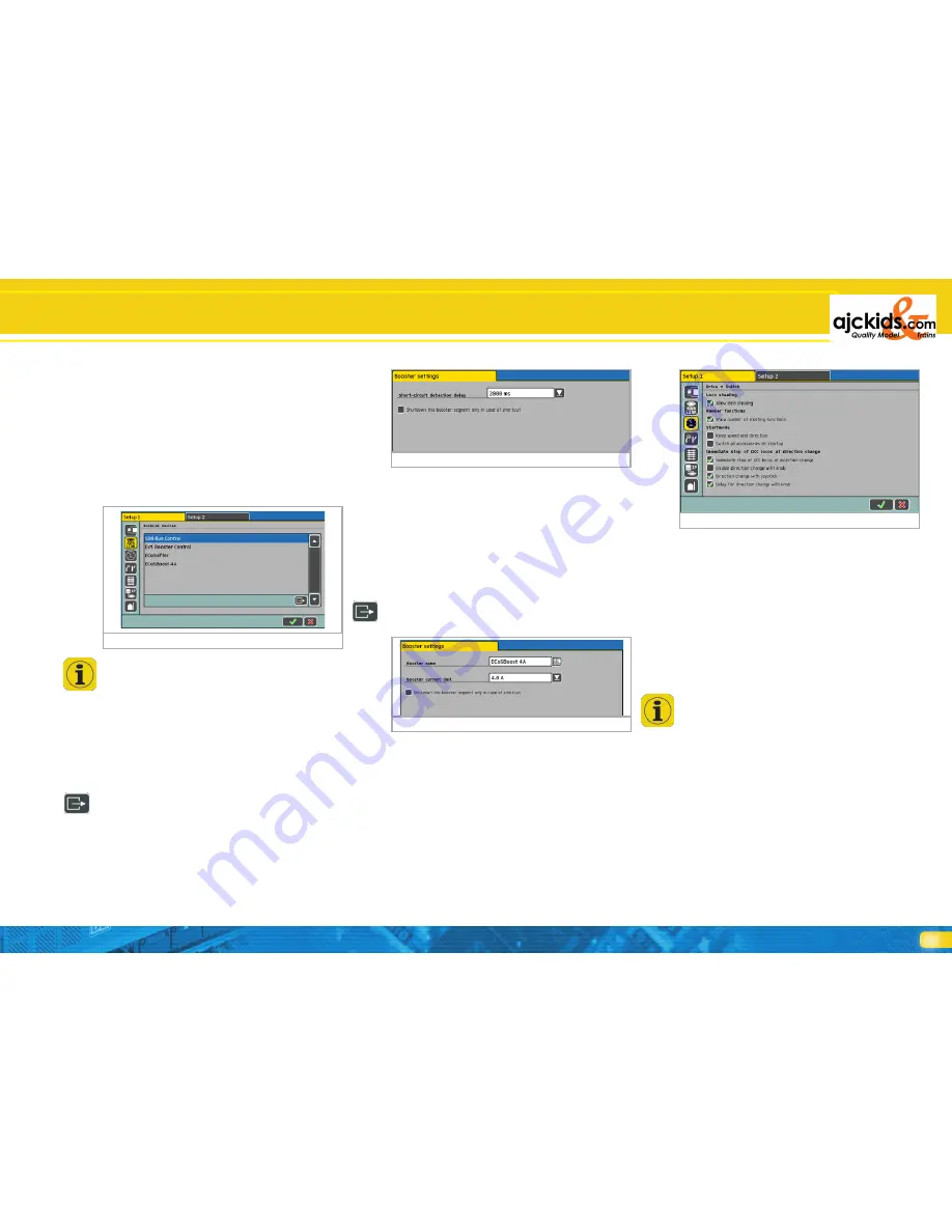
Figure 100
For safety reasons the button „Reset“ is normally shaded grey.
Before activating a reset you have to permit access to this func-
tion as described in chapter 21.6.
21.1.5. Restarting the ECoS
Restarting the ECoS is done by pressing the screen button “Re-
start the ECoS”. All settings remain intact. Such a restart may
resolve some software issues and takes considerably less time
than a complete shutdown and a new booting procedure.
21.2. Devices in the system
In this menue all devices that are currently connected to the
ECoSlink bus. Each device reports automatically to ECoS (Plug
& Play) and generally can be configured further if required.
The devices “ECoSniffer“, “s88-Bus Control” and “External
Booster Control” will always be displayed even if there are no
external devices connected. ECoSlink These three devices are
integrated into ECoS but are displayed via the ECoSlink as if
they were external.
21.2.1. 6021 and DCC booster configuration
As mentioned in chapter 8.7 different booster types use dif-
ferent methods for detecting a short circuit. The time it takes
from detecting a short circuit until ECoS turns off the track
power must be adjusted to the type of booster to assure safe
operations and to avoid erroneous switch-offs.
These settings are adjusted in the sub-menue “Booster Con-
figuration”.
You find this menue via the set-up menue “Configuring De-
vices” as per figure 97: Select “External Booster Control” from
the list of devices and press “Edit”.
Then enter the delay time directly in “Delaying Short Circuit
Detection”:
• Select “0 ms” for DCC compatible boosters (e.g. Lenz)
• Select “1500 ms” for LDT boosters
• Select “2000 ms” for Märklin® 6017-boosters
Start with “0 ms” for all other makes and test it.
Figure 97
Make sure that both a Motorola®- and a DCC-loco are active.
Some boosters cannot handle DCC packets very well. Should
ECoS switch off immediately (STOP button is illuminated red)
then the time must be increased.
If you set the tick behind “Ignore short circuit in other boos-
ter circuits” the internal booster does not switch off whenever
other boosters report a short circuit. Thus the internal booster
only switches off if a short circuit occurs in its own district.
21.2.2. ECoSBoost configuration
For each ECoSBoost booster connected you can set the current
threshold individually.
Simply choose the desired booster from the list “Devices in the
system” and select the configuration menu.
Name
Enter the desired name. This way you can keep your boosters
apart. If you have several
ECoSBoost boosters you should plug them into the command
station and configure them one by one in order to keep eve-
rything organised.
Current
If you wish you can reduce the maximum current with the
choice list “Current”. Never set the current to a higher level
than necessary in order to avoid any damage or welded rails in
case of a short circuit.
If you place a tick behind the remark “Ignore other boosters”
then the internal booster of the ECoS will
not
be turned off
whenever other boosters report a short circuit. Thus you can
set the system so that the internal booster will only be switched
off if a short circuit occurs in its own district.
21.3. Train operations mode
21.3.1. Taking over locomotives
If you place a tick in front of “Taking over locomotives” then
you can take over (“pinch”) a locomotive from another cab at
any time (parallel operation).
21.3.2. Numbering functions
If this feature is active, then the function buttons (symbols) are
numbered in order to make it easier to keep them apart. A
small number will appear at the bottom right of each function
button symbol. This feature is active ex works.
21.3.3. Starting mode
21.3.3.1. Starting mode for locomotives
Here you determine if operating parameters of locomotives
(speed, function status, direction) should be transmitted to the
individual locomotives after turning on the ECoS in the same
manner as they were set prior to the last shut down.
Thus you are in a position to continue to play exactly where you
left off in the previous operating session.
21.3.3.2. Turnout control starting mode
Here you determine if the command station should transmit a
switch command to each accessory after initialisation. This is
particularly useful in semi- or fully-automatic operating mode
in order to assure that all turnouts and signals are set precisely
as they should be.
Thus any possible manual changes of aspect while the com-
mand station was turned off will be corrected.
Configuration Menue
Figure 98