background image


30 


o


Touchscreen pen 

o


Silicon cloth                     


Power cable (European cable and Hospital Grade cable) 


MYOPIA EXPERT 700 dust cover 


MYOPIA EXPERT 700 user manual 

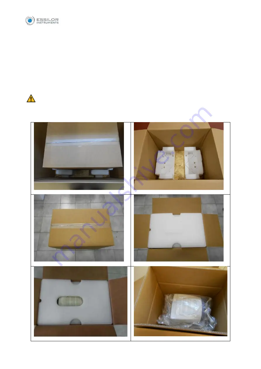
Open the internal box and remove the specially shaped part that holds the instrument. Remove the Nylon 

cover.  


 Be careful when taking MYOPIA EXPERT 700 out of the box, gripping it by the chinrest arch and the 

base beside the joystick. The instrument can now be taken out of the package. The steps are illustrated in 

Fig. 5: 


Summary of Contents for MYOPIA EXPERT 700

Page 1: ...MYOPIA EXPERT 700 Biometer USER MANUAL Rev 1 07 04 2021...

Page 2: ...tly from the product you purchased The manufacturer also reserves the right to make any changes to this manual without notice The original text of this manual is in English SW v 1 0 0 BMT1IV Manufactu...

Page 3: ...nity 9 3 SYMBOLS 11 3 1 Device Sample Labeling 13 4 SAFETY INSTRUCTIONS 14 4 1 General 14 4 2 Environment Of Use 15 4 3 Electrical Safety 15 4 4 Led Emission Safety 15 4 5 Installation with External D...

Page 4: ...Checking Calibration 37 12 4 Entering Selecting a Patient 41 12 4 1 Creating a new patient 42 12 4 2 Selecting or editing a patient 42 12 4 3 Patient data management 43 12 4 4 Open an examination or...

Page 5: ...1 9 3D 72 14 1 10 Edit Rings 72 14 2 OD OS 74 14 3 ZER Zernike 75 14 4 Height 78 14 4 1 Profile 79 14 4 2 3D 80 14 5 COMP Comparison 81 14 5 1 DIFF Differential 83 14 6 PUP Pupillometry 84 14 6 1 Disp...

Page 6: ...17 5 2 Network Folder 110 17 6 Connectivity 111 17 6 1 Server List 111 17 6 2 Export to External Software settings 111 17 6 3 XML Export 111 17 6 4 DICOM 111 17 7 Admin 113 17 7 1 Remote Assistance 1...

Page 7: ...7 8 5 Password protect exported PDF reports 119 17 8 6 Hide Patient Names and Disable Actions when in assistance mode 119 18 MYOPIA EXPERT 700 TROUBLESHOOTING 121 19 MYOPIA EXPERT 700 TECHNICAL SPECIF...

Page 8: ...easy observation of changes over time For example it is especially useful in the case of myopia Eye specialists ophthalmologists opticians and optometrists The instrument must be used by qualified per...

Page 9: ...or assessing cornea s artefacts and the lachrymal film rupture time Analysis of wave front corneal aberrations generated by the front surface of the cornea with Zernike analysis information on the op...

Page 10: ...ean and dust free This product complies with EMC standards IEC 60601 1 2 4th Edition ELECTRICAL MEDICAL DEVICES require special EMC precautions and must be installed and activated per the EMC instruct...

Page 11: ...c discharge ESD IEC 61000 4 2 8kV contact 15kV air Electrical fast transient Burst IEC 61000 4 4 2kV 100kHz repetition frequency Surges IEC 61000 4 5 1kV common mode 2kV differential mode Rated Power...

Page 12: ...of the communication equipment Rated maximum output of transmitter W Separation distance according to transmitter frequency m 150kHz to 80MHz 80MHz to 800MHz 800MHz to 2GHz 0 01 0 12 0 12 0 23 0 1 0...

Page 13: ...LOW THE INSTRUCTIONS FOR USE ISO 7010 W001 GENERAL WARNING ISO 7010 W001 CAUTION GENERAL WARNING TO AVOID INJURY CAUSED BY ELECTRIC SHOCK DO NOT OPEN THE COVER ASK YOUR DEALER FOR SERVICE ISO 7010 W00...

Page 14: ...can be safely exposed EN ISO 15223 1 KEEP DRY Specifies a medical device that needs to be protected from moisture ISO 7000 0621 FRAGILE HANDLE WITH CARE ISO 780 THIS WAY UP Specifies the correct upri...

Page 15: ...13 3 1 DEVICE SAMPLE LABELING...

Page 16: ...t to disconnect the plug for connection to the supply line If the device has just been delivered or underwent thermal shock wait at least one hour before making measurements on patients If the device...

Page 17: ...ials or in areas at risk of explosion 4 3 ELECTRICAL SAFETY To avoid the risk of electric shocks this equipment must only be connected to the supply mains with protective grounding MYOPIA EXPERT 700 h...

Page 18: ...n Device is defined in clause 16 5 of IEC 60601 1 In case a Multiple Socket Outlet is used to supply the system a Medical Electrical System has been created even if there is no signal connection to ot...

Page 19: ...a coupling in IEC 60601 1 2005 Do not change the Ethernet settings of the INTERNAL or RESERVED adapter If a specific configuration for the LAN network is needed the settings can be modified accordingl...

Page 20: ...her patient clean the mounting brackets that come into contact with the forehead and chin using neutral detergents 4 8 CHECKING THE MEASUREMENTS It is recommended to check the calibration of the instr...

Page 21: ...ified or identifiable natural person data subject an identifiable natural person is one who can be identified directly or indirectly in particular by reference to an identifier such as a name an ident...

Page 22: ...t of Access by the data subject The controller and processor have access to data related to the subject which can be stored on the device and can make the data available to the subject in the normal o...

Page 23: ...ns When the on board application is started the first time the following prompt is shown By pressing the OK button you get access to the Privacy Security settings of the application where you can defi...

Page 24: ...22...

Page 25: ...t use of the device The product warranty is valid only if the device is equipped with its original accessories If the device is opened by unauthorized staff the manufacturer shall be held harmless fro...

Page 26: ...24 6 LEGAL PROVISIONS 93 42 EEC 2007 47 EC Class IIa medical device IEC 60601 1 Class I type B continuous operation IEC 60601 1 2 see EMC Table ISO 15004 2 Group 2 UNI EN ISO 19980 Type A...

Page 27: ...ire earthquakes actions by third parties and other accidents or negligence and misuse of the instrument by the user The manufacturer shall in no way be liable for damages caused by the user or by the...

Page 28: ...26 8 MAIN COMPONENTS Fig 1 Patient s side 1 FOREHEAD REST 2 PLACIDO DISK 3 CHINREST 4 Locking pins for chinrest paper 5 Chinrest monitor...

Page 29: ...TOUCHSCREEN 2 JOYSTICK 3 STAND BY BUTTON Power connector with fuse carrier 2 x USB port 1x LAN port NB The parts in contact with the patient applied parts are the forehead rest and the chinrest in Ac...

Page 30: ...ows the serial number of the instrument with which it is associated To properly check calibration the calibrator provided with the instrument must always be used Power cable CD User Manual English Use...

Page 31: ...ts original packaging which is specifically designed to protect it against damages 10 1 INSTALLING THE SYSTEM Before installing the system read the Safety Instructions in this manual Fig 3 shows the c...

Page 32: ...700 user manual Open the internal box and remove the specially shaped part that holds the instrument Remove the Nylon cover Be careful when taking MYOPIA EXPERT 700 out of the box gripping it by the c...

Page 33: ...ed The instrument is now ready for use 10 2 UNINSTALLING THE SYSTEM Take the original packaging Set the instrument to the minimum height using the joystick Lock the device using the instrument semi lo...

Page 34: ...32 Follow the step sequence shown in Fig 7 Fig 7 Put the accessories in the dedicated spaces Close the external box with strong packing tape or use extensible film and packing straps...

Page 35: ...1 STAND BY BUTTON 2 POWER CONNECTOR 3 LAN PORT 4 USB PORT 2 11 2 POWER ON PROCEDURE Make sure the power cord provided is connected to the supply mains Press the standby button and wait for the system...

Page 36: ...on simply touch the screen at the command The screen is highly sensitive Gentle and slight pressure is required and strongly recommended 12 1 USER LOGIN LOGOUT The user MUST configure the login passwo...

Page 37: ...device locks automatically if no user actions occur for a configurable amount of time The MYOPIA EXPERT 700 screen saver is then shown To unlock touch the device s screen If the login password is con...

Page 38: ...n layout Below is shown a sample of the acquisition screen Fig 9 1 The active working area is highlighted in orange 2 Main Menu 3 Print 4 Settings 5 Left Eye Data 6 Live images from camera 7 The measu...

Page 39: ...aminations When the device has been transported from one place to another When it has suffered an impact or thermal shocks To check the calibration turn on the device and when asked to check the calib...

Page 40: ...chinrest and press until the tool is blocked on the device Check that the calibration tool is perfectly aligned with the device If the calibration tool is positioned correctly all the rings of the Pla...

Page 41: ...rect the words Repeat or Not Valid will be displayed beside the wrong measurement See the table below for instructions MESSAGE MEANING WHAT TO DO OK Good calibration Click on Main to start a new exami...

Page 42: ...ration clean the sphere of the calibration tool make sure that the calibration tool is positioned correctly If the calibration check is still not valid do not take any patient measurement and contact...

Page 43: ...on the software displays the following screen To continue the examination you must always enter a patient or select one from the database or server if enabled Fig 15 Fig 15 shows the section for crea...

Page 44: ...e entered simply by touching and holding the corresponding letter Fig 16 Fig 16 12 4 2 Selecting or editing a patient On the input screen tap on the List tab to access all the patients found in the da...

Page 45: ...ocal data Maintain existing data discard entered data Use entered data Replace the already existing patient data with the data just entered 12 4 4 Open an examination or acquire data for the selected...

Page 46: ...of his exams possibility to export to USB or press Cancel to abort From the list of patients select the patient you want to edit a form will be opened to editing it Press Ok or Cancel to confirm or c...

Page 47: ...nt day The list can be filtered by one or more of the following criteria Patient Name Patient ID Examination date range Scheduled Station Name default is MYOPIA EXPERT 700 Mode default is OT contact D...

Page 48: ...k steadily at the fixation point in the center of the Placido disk The correct alignment with the patient s pupils can be visually checked by the operator referring to the two lines on the forehead su...

Page 49: ...he joystick adjustment is not enough to achieve the correct position Fig 22 The position of the chinrest must be both comfortable and correct i e it must allow the person measuring to focus on the fix...

Page 50: ...ese indicate the eye being acquired the one highlighted in yellow they are selected automatically depending on the position to which you move the instrument TOPO BIO gives access to the topographic an...

Page 51: ...played press the joystick button again and the system will automatically capture the required image and or measurements Do not move the joystick during acquisition which lasts just a few seconds The F...

Page 52: ...in red The blue arrows indicate to move the instrument backward away from the patient The centering condition is displayed in blue The green signs indicate that the ideal focus has been reached Press...

Page 53: ...in multiple measurements movement and measurement not in range The possible problems in acquisition are found in the software with the following methods Error cause Identification Closed eyelid Missin...

Page 54: ...nce between the cornea and the inner limiting membrane because the sound waves are reflected at this membrane To ensure that the measured values obtained with the MYOPIA EXPERT 700 are compatible with...

Page 55: ...24 rings of the Placido disk at a distance of 80 millimeters from the patient s eye The position of the device in relation to the patient s eye thus found is used as a starting point for fine adjustme...

Page 56: ...controlled light conditions Photopic Mesopic controlled light conditions Mesopic Scotopic controller light conditions Scotopic Fig 26 In the case of dynamic pupillometry recording of the state of the...

Page 57: ...of pupillometry in mesopic lighting conditions can be difficult to accomplish 12 9 FLUORESCEIN Press the FLUO button to access the fluorescein analysis acquisition environment Fig 27 You can select be...

Page 58: ...he RX AL Trend button it is possible to access the Data Review the RX AL Trend data overview section for the selected patient The number inside the blue circle over the RX AL Trends button shows the c...

Page 59: ...700 and stored onboard together with manual data eventually imported or added BASELINE Starting condition of the trend profiles It can be changed on the fly to any examination date MONTH BASE Window...

Page 60: ...58 RX AL Refraction Axial Length trend Combined trend view with Refraction error S E and Axial Length...

Page 61: ...raction trend Refraction S E absolute value at reference Vertex Distance trend and yearly variation on 3 6 12 months basis AL Axial Length trend Absolute Value trend and yearly variation on 3 6 12 mon...

Page 62: ...12 months basis DATA Raw data table review and management edit delete General action buttons Import Button Import data from the template sheet for the current patient only Add Button Add data manuall...

Page 63: ...61 Delete Button Delete the selected row...

Page 64: ...k the RX AL Trend report A binocular report with Refraction and Axial Length absolute and yearly variation charts Data table Notes list SCREENSHOT create a report page with the current view Available...

Page 65: ...Topography Map OD OS or R L Right to Left side by side Topography Map review ZER Zernike Analysis HEIGHT Altimetric Map COMP Topography Map comparison of two different exams of the same patient PUP Pu...

Page 66: ...been acquired In the right column you can select the following options Absolute or Normalized absolute scale or standardized scale with related step Axial or Tangential axial map or tangential map Dis...

Page 67: ...mm zones as shown in Fig 28 14 1 3 Keratorefractive indexes Press the I button to view the keratorefractive indexes Fig 29 Fig 29 Astigmatism Astigmatism at 3 and 5 mm Pupil Avg Average pupil power fo...

Page 68: ...al Asphericity window could also be invoked from the Corneal Height Map environments In this case as in the topographic map the user should choose the Asphericity Corneal menu item Asphericity Fig 30...

Page 69: ...Asphericity present in the settings environment Peripheral degrees The table describes the corneal asphericity at the different peripheral degrees see Fig 31 Fig 31 The first four rows of the table de...

Page 70: ...r zones centered on the vertical axis of the ruler and placed in the lower hemisphere and the upper hemisphere of the cornea respectively Kpi Keratoconus diagnosis probability index Based on the combi...

Page 71: ...tude Index based on the axial map Tangential map CLMI Cone Location and Magnitude Index based on the tangential map DSI Differential Sector Index PPK Percent Probability Keratoconus Display CLMI allow...

Page 72: ...m the optical axis Avg Pupil Mean diameter of the pupil Fig 34 14 1 6 Gallery Press the icon at the top right of the map to enter the gallery Fig 35 Fig 35 From the gallery you can change the default...

Page 73: ...tton at the bottom right corner Fig 36 14 1 8 Profile Press the Profile button to view the curvature profile along the most curved meridian and the flattest meridian red and blue The difference is dis...

Page 74: ...1 9 3D Press the 3D button to view the 3D map of the keratometric data Fig 38 Fig 38 14 1 10 Edit Rings In this section the user can edit the 24 rings in order to improve the topographic map Fig 39 F...

Page 75: ...ou wish to edit In the central area three buttons are available 1 Delete Points to delete parts of the selected ring 2 Delete Ring to delete all of the selected rings 3 Delete All to delete all the 24...

Page 76: ...you can compare the OD and the OS data on the same screen Fig 50 Fig 40 As in the Map section you can switch between the K I KC and P tabs The DIFF button is disabled because the difference map is al...

Page 77: ...RMS value This allows you to quantify the deviation with respect to an ideal wavefront On entering the module the aberration map is displayed Maps section Histograms of the Zernike expansion coefficie...

Page 78: ...front in the retina Spot Diagram represents the spatial distribution of the wavefront over the retina Visus Visus Low Contrast represents the patient s real vision with high and low contrast The data...

Page 79: ...77 Fig 43 It is possible to switch between ETDRS and Landolt C Visus simulation view...

Page 80: ...n change the Radius Flat 2 Aspherical the user can change the Radius Flat and Asphericity 3 Asphero Toric the user can change the Radius Flat Toricity and Asphericity 4 Differential the user can selec...

Page 81: ...le button to view the curvature profile along the steep meridian or the flat meridian Fig 56 It is possible to scale the graph with the 50 m 10 m and 5 m buttons found under the graph Press the Close...

Page 82: ...80 Fig 46 14 4 2 3D Press the 3D button to view the 3D map of the altimetric data Fig 47 Fig 47...

Page 83: ...compare the current exam data with the data of another exam for the same patient Fig 48 Fig 48 When you select the COMP button the interface shown in Fig 49 appears and the software allows you to cho...

Page 84: ...e related paragraph The user can also change MAP it is possible to choose between axial and tangential SCALE it is possible to choose between absolute and normalized for the normalized map the user ca...

Page 85: ...re the main indexes of the respective maps Above the differential map four differential values appear after tapping on the differential map P is the difference between the dioptric power r is the diff...

Page 86: ...or left eye respectively With the patient s eye in view the buttons will be located below the home screen These buttons are used to navigate between the acquired frames The current frame is shown next...

Page 87: ...Scotopic By tapping on the Photopic Mesopic Scotopic buttons static pupillometry acquisitions will be displayed with the following information Value of the average pupil diameter measured for all the...

Page 88: ...n concentric circles identify the decentration of the pupil center with respect to the fixation point The red line on the other hand represents the coordinate variations during the acquisition of dyna...

Page 89: ...e the pupil contraction phase following a change in brightness brought about by the LEDs coming on Blue for the pupil dilation phase following the change from LEDs on to LEDs off NB These graphs are o...

Page 90: ...lery When the fluorescein module is started the first acquisition in the gallery is displayed in the main window Tapping on a picture this is displayed in the main window Tapping on a video it is play...

Page 91: ...llows you to view the value of the corneal diameter calculated from the limbus Fig 56 Fig 56 Tapping on the Open button in the Edit menu Fig 57 the user can manually reposition the positional indicato...

Page 92: ...tion deviation from the center of the iris with respect to the fixation point By changing the position of the indicators also the values of corneal diameter and the offset of the visual axis x and y a...

Page 93: ...report are available only in the related sections Report settings the user can change the settings for report printing Output devices the user can choose where he she wants to export the selected rep...

Page 94: ...92 Fig 59...

Page 95: ...e lens manufacturer under the setting which you set up in advance and visualizes the calculation results Please note that this result does not represent the patient s actual status when he or she wear...

Page 96: ...ress the Add button To cancel all the lenses shown in the gallery press the Reset button Instead if you want to delete a single lens you must tap on the Recycle Bin icon If more than three lenses are...

Page 97: ...s also possible to edit these values by pressing the button found under the values a tab will appear Fig 62 and the user will be able to edit the values by pressing the related arrows found at the rig...

Page 98: ...namely Keratometric data Corneal diameter Fig 63 In this section it is also possible to edit the limbus by tapping on the Edit button By pressing this button the user will be required to select three...

Page 99: ...ilting and decentration of the selected lens Fig 64 Fig 64 The user can edit the tilt values by tapping on the yellow squares found around the lens and the decentration values by dragging using their...

Page 100: ...n the user can see the distance between the selected lens and the patient s cornea in a graph Fig 65 Fig 65 The user can select the meridian where the distance is displayed by tapping on the arrows fo...

Page 101: ...e button Fig 66 The settings screen is divided into the following categories General Measurements RX AL Trends Lenses Report Connectivity Admin From each setting environment you can close and return t...

Page 102: ...rrent system date and time by tapping on the Edit button Pointing Devices Toggles the mouse cursor on or off OD OS Notation To select how to indicate the eye being acquired in two different notations...

Page 103: ...ng and displaying fluorescein and pupillometry Fig 67 Fig 67 17 2 1 Scales Map Select a unit of measure Diopters Millimeters This option is activated both for the acquisition screen and for the topogr...

Page 104: ...ve Scale Colors Select between two color scales options Color Mode 1 Absolute scale Color Mode 2 Absolute scale Decentration Format Select a decentration format Cartesian Polar 17 2 2 Fluorescein Fluo...

Page 105: ...n 17 2 4 Map Option Map Draw Select one or more items to customize the map display Meridians Zones Ruler Grid Keratometry Select one of the keratometric indexes Sim K Meridians Emimeridians 3 5 7 mm o...

Page 106: ...ettings icon you get access to the RX AL Trend related options Time Axis Options The charts shown in the Data Review section can have the time axis visualized by Date calendar date of examination data...

Page 107: ...t already existing in the archive will be matched by ID A patient not present in the archive a new patient will be created if at least ID and date of Birth are specified in the sheet otherwise the dat...

Page 108: ...the archive The Dates patient DoB and Exam Date will be parsed according to the Date Format selected in the settings of the application Not compatible dates will cause the row to be ignored If in rela...

Page 109: ...e o Eye status condition at the moment of refraction measurement Cycloplegia or Normal o Contact Lens data in case of Over Refraction measurement Lens Power SE in Diopters Base Curve of contact lens i...

Page 110: ...database You can import new manufacturers using a USB pen drive Check the manufacturers you want to include in the list of available lenses for the contact lens fitting module Select the desired brand...

Page 111: ...d at the top of the report page Fig 69 Fig 69 17 5 1 Report Settings It allows the user to set the default paper type and to choose whether the report will be for one eye or both It is possible to set...

Page 112: ...ver path_on_server Domain name optional and user name user name associated to an optional domain name that have the authorization to access to a specified network folder path Note if the specified net...

Page 113: ...ters for the connections to the available DICOM services The available services are Worklist Mode The DICOM Worklist Mode provides a list of imaging procedures that have been scheduled for performance...

Page 114: ...ault is 115 The connectivity to the defined server can be tested using the C ECHO function activated by the related Connection Test button The result of the connection test is shown by the green or re...

Page 115: ...n the procedure It is recommended to check the calibration when the device has been transported from one place to another and if it suffered an impact or thermal shocks It is recommended to check the...

Page 116: ...unit Go to Settings Admin and press Remote Assistance Wait for the Team Viewer Window to open Communicate to the Remote Operator the ID shown under Your ID and wait for the incoming connection The pa...

Page 117: ...he software perform the following operations 1 Put the upgrade package in the root main card of an empty FAT32 formatted USB external drive 2 Switch on the MYOPIA EXPERT 700 3 Click on the settings ic...

Page 118: ...oot and starts the MYOPIA EXPERT 700 application 9 If you see the message shown in Fig 73 please switch off your MYOPIA EXPERT 700 and turn it on again Your MYOPIA EXPERT 700 should now work fine Fig...

Page 119: ...the Network configuration buttons open respectively the printer management and the network configuration panels of Windows that allow to manage the printers and the network properties of the device N...

Page 120: ...define the preferred password It is recommended to use a strong password The password is case sensitive No password strength checks are applied It is recommended to apply a password aging policy Type...

Page 121: ...password is enabled and configured If this option is enabled the PDF reports exported to the network shared folder will be accessible only by typing the user password as defined to access the MYOPIA...

Page 122: ...s and related actions are regularly accessible Technician Mode In technician Mode the patient details are not accessible and delete edit actions are not available When exporting exam packages in this...

Page 123: ...nical Service After switching on the MYOPIA EXPERT 700 only a blue screen appears Contact Technical Service The MYOPIA EXPERT 700 is on but the on board application is not active Turn off the device f...

Page 124: ...annot view previously saved examinations If the problem persists contact Technical Service Cannot save new examination data Contact Technical Service Cannot print Reports Check that some reports are s...

Page 125: ...E For the isolation of the device from the supply mains the device is provided with a removable power cable GENERAL INFORMATION FUNCTION FEATURES LIGHT SOURCE Corneal topography and Keratometry Kerato...

Page 126: ...Fixation 572 15 360 mcd 0 01mW Cone Blue led Fluorescein analysis Blue leds 475 25 900 mcd 0 207mW Cone IR LED 940 Pupillometric analysis Infrared 940 45 20 mW sr 0 03mW SLED Interferometer Axial Bio...

Page 127: ...ature Min Max Min Max Min Max 10 C 40 C 20 C 70 C 20 C 70 C Relative humidity 8 75 non condensing 8 75 non condensing 8 75 non condensing Atmospheric pressure 800 1060 hPa 700 1060 hPa 700 1060 hPa EL...

Page 128: ...ve 93 42 EEC implemented in Italy by Legislative Decree n 46 97 with Annex II excl 4 and subsequent amendments and additions Directive 2007 47 CE implemented in Italy by Legislative Decree n 037 10 fo...

Page 129: ...er using a screwdriver Step 2 Take out the fuse box use a screwdriver to release it Step 3 Remove the blown fuse from its seat and replace it with an identical one as shown in the table below and on t...

Page 130: ...n la web Para acceder escanee el c digo QR que se encuentra a continuaci n con la ayuda de una aplicaci n T ielik kasutusjuhend on saadaval veebis Juurdep suks palun skannige allolevat QR koodi kasuta...

Page 131: ...a acessar scanear o c digo QR abaixo ro ru sk sl sr sv th tr uk vi zh usando a respetiva aplica o Versiunea integral a manualului de utilizare este disponibil pe un site web Pentru a l accesa scana i...

Page 132: ...s product Product name MYOPIA EXPERT 700 Software version as written in the Settings Admin section Period of use Please provide the date of installation Defective condition Please provide as many deta...

Reviews: