


78
14.4
H
EIGHT
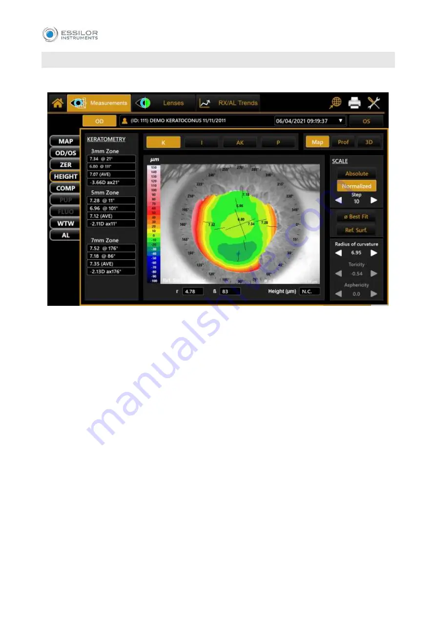
“Height”
environment allows the user to compare the patient’s cornea with a reference surface (
Fig. 44
In the right column, it is possible to:
Choose between the
“Absolute”
and
“Normalized”
scale, with the possibility to change the
normalized scale step.
Choose the
“Best Fit Diameter”
and select the best fitting diameter in the range from 3mm to 8mm.
Choose the
“Reference Surface”
and select the following surfaces:
1.
Spherical: the user can change the
“Radius Flat”
.
2.
Aspherical: the user can change the
“Radius Flat”
and “
Asphericity”
.
3.
Asphero
–
Toric
: the user can change the “Radius Flat”, “Toricity” and “Asphericity”.
4.
Differential
: the user can select the image of another exam of the same patient to compare it
with the current exam (Fig.45).
By tapping on any point of the map, the software will provide the following information:
r
: the distance of the point from the center of the image in polar coordinates.
lb
: the angle of the distance r.
Height
: the distance between the patient’s cornea point and the reference surface point.
In the altimetric mode, it is still
possible to see the “K”, “I”, “KC” and “P” tabs
.
Summary of Contents for MYOPIA EXPERT 700
Page 1: ...MYOPIA EXPERT 700 Biometer USER MANUAL Rev 1 07 04 2021...
Page 15: ...13 3 1 DEVICE SAMPLE LABELING...
Page 24: ...22...
Page 63: ...61 Delete Button Delete the selected row...
Page 79: ...77 Fig 43 It is possible to switch between ETDRS and Landolt C Visus simulation view...
Page 94: ...92 Fig 59...