Page 11
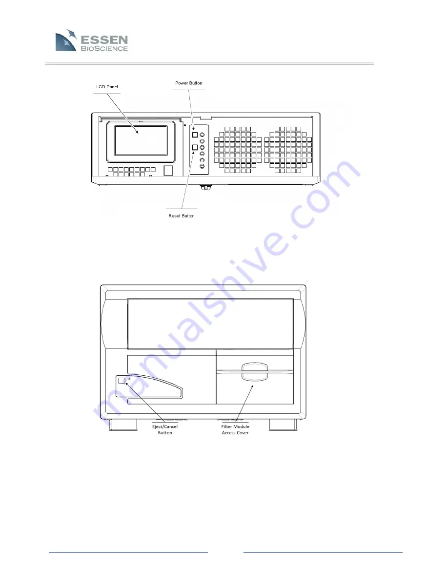
Figure 3.
Controller front view with access door open
Figure 4.
Microscope front view
Page 1: ...Page 1 IncuCyte ZOOM Users Manual 2013A Essen BioScience Inc www EssenBioScience com...
Page 2: ...tures 10 3 2 Removing the Shipping Pin 12 3 3 Installing the Filter Module 13 3 4 Installing an Objective 14 3 5 Positioning the Controller 14 3 6 Placing the Microscope into the Incubator 15 3 7 Swit...
Page 3: ...ell Culture Monitoring and Data Analysis 27 7 1 Introduction 27 7 2 User Interface 28 7 3 Scheduling Scans and Loading Vessels 29 7 3 1 24 Hour Repeating 29 7 3 2 Scan on Demand 34 7 4 Finding and Vie...
Page 4: ...s 82 Chapter 8 Special Modules and Scan Types 85 8 1 Scan Types available with Essen ImageLock 85 8 1 1 Standard with Lock 85 8 1 2 Scratch Wound 85 8 2 Cell Migration Invasion Module 86 8 3 Angiogene...
Page 5: ...that prove to be defective For warranty service or repair this product must be returned to the Essen factory Buyer shall prepay shipping charges to Essen and Essen shall pay shipping charges to return...
Page 6: ...trast only 4459 IncuCyte ZOOM HD Dual Color Filter Cube High Definition Phase Contrast Green and Red Fluorescence 2 3 Safety has Priority Please note the following directions for safe and problem free...
Page 7: ...n Garden City Hertfordshire 26 1 Sakuragaoka cho Tel 1 734 769 1600 AL7 3AX United Kingdom Shibuya ku Tokyo Fax 1 734 769 7295 Tel 44 0 1707 358688 150 8512 Japan ussupport essenbio com Fax 44 0 1707...
Page 8: ...system to a new location The IncuCyte ZOOM System is shipped in two boxes one containing the automated microscope and the other containing the controller NOTE The IncuCyte ZOOM consists of 2 componen...
Page 9: ...places it on a stable work surface The unit should then be removed from its plastic bag not shown in Figure 1 and inspected for any obvious signs of external damage The controller should be removed f...
Page 10: ...turn the unit Chapter 3 Installation of the IncuCyte ZOOM Hardware 3 1 IncuCyte ZOOM Hardware Features The diagrams below Figure 3 and Figure 4 identify many of the hardware features buttons connectio...
Page 11: ...Page 11 Figure 3 Controller front view with access door open Figure 4 Microscope front view...
Page 12: ...n proceed Remove the filter module access cover by pushing it down and pulling the cover out The pin will be visible as in Figure 5 below To remove the pin depress the button in the center of the T ha...
Page 13: ...ed in the accessories box with your ZOOM With the filter module access cover removed pull out the drawer about halfway in order to get better access Remove the plastic cover from the filter module mou...
Page 14: ...ay to provide access Remove the objective bracket from the system by loosening the screw using the supplied 2 5mm T handle hex wrench and then pulling the bracket straight out Finger tighten the objec...
Page 15: ...cables from the microscope out through the cable access port on the back or side of the incubator The cables can usually be routed up a corner of the incubator so as not to interfere with the install...
Page 16: ...er switch When the system is running it may take 30 to 60 seconds for the system to save any settings and data before it powers down If the system fails to power down press and hold the power switch f...
Page 17: ...warm up procedure afterwards then an auto warm up process will be initiated The auto warm up is NOT intended as a substitute for the manual warm up cycle but rather it is a backup process that occurs...
Page 18: ...Dynamic Host Configuration Protocol Follow the procedures described in Section 4 1 DHCP Based Networks to connect to this type of network If the network is not configured to assign IP addresses dynami...
Page 19: ...right of this text and type the following ZOOMXXXXX followed by the Enter key 4 If the controller is found on the network you will be prompted for a User name and password Press the Cancel button to...
Page 20: ...ll that the ultimate goal is to configure the controller s primary Ethernet port with a static IP address selected for your corporate network Once on the desktop the controller s primary Ethernet port...
Page 21: ...e a destination folder and Install 4 If prompted install the Windows Media Encoder Required to save movies 5 Close the installer when completed 5 3 Connecting 5 3 1 Setting the Date and Time The IncuC...
Page 22: ...ers to set and change their own passwords This function is available to Users at all permission levels The Create User and Delete User functions however are only available to Users with the Administra...
Page 23: ...y the instrument To insure reliable and proper operation of your IncuCyte the factory settings of the controller operating system should not be altered However we recognize that there may be instances...
Page 24: ...primary Ethernet port install security software etc Please consult with your IT department for answers to questions related to your local network configuration and security software Chapter 6 Calibrat...
Page 25: ...gure 12 The status if the Calibration and Confirm test completed successfully will be displayed in the far right column of the table labeled Result pass fail status is reported for each magnification...
Page 26: ...e front position of the IncuCyte ZOOM Fluorescence calibration requires use of the front tray position and the remaining positions can be occupied with trays at the time of calibration 2 Load a calibr...
Page 27: ...Type Test The log will also state whether or not the calibration passed If the calibration failed the log will include recommendations to avoid potential issues the next time through Chapter 7 Cell C...
Page 28: ...ablished assays is represented below All aspects of live content imaging using the IncuCyte ZOOM software are described in detail within this chapter 7 2 User Interface Once connected to an IncuCyte Z...
Page 29: ...ur Repeating vertical tab is selected you will be required to enter information that defines your specific assay 7 3 1 1 Vessel selection In the Drawer Setup pane determine which tray position front m...
Page 30: ...microplates or sector flask dish The Scan Pattern is displayed within the software as a pattern of green squares where each square represents one image Create new scan patterns by using the edit scan...
Page 31: ...ated and applied to a vessel a small plate map icon will appear next to the plate map button Refer to section 7 9 Plate Map Editor Notes Any extra information desired 7 3 1 4 Scheduling Identical Assa...
Page 32: ...ay Scan Bar will now be displayed Hold the mouse over the Scan Bar to display the exact scan start time and scan length 2 The scan start time can be adjusted by right clicking on the bar to adjust the...
Page 33: ...selected 7 3 1 8 Place Tray and Vessel in IncuCyte Place the appropriate tray refer to section 7 8 1 Selecting and Placing Trays and vessel in the pre determined position within the IncuCyte Allow ti...
Page 34: ...sting information into the Unique ID field or a Unique ID correlating to the current year day time will be assigned to the Scan on Demand vessel This information can be used to link subsequent scans t...
Page 35: ...7 4 1 1 View Scans Tab When the ZOOM IncuCyte software is launched it opens by default to the View Scans screen The first time the software is opened the screen will be empty However once scans have b...
Page 36: ...her functions which are listed in the table below Refer to Table 4 for details NOTE Because the column search tools use the and function to filter Users are able to filter scanned vessels using multip...
Page 37: ...isplayed View images from a specific scan time by clicking directly through the Time Tree or by using the forward or back buttons located below the Time Tree 7 4 2 3 Vessel Image The selected flask di...
Page 38: ...ortion of the image with a pixel intensity value less than or equal to the Minimum Intensity will be assigned a relative brightness equal to the darkest possible value in the image in this case black...
Page 39: ...oval of the red fluorophore from the green channel using the spectral unmixing tool Bottom Row We lowered the green fluorescent channel to show the difference between optimized and overcorrected spect...
Page 40: ...e ZOOM software separates data processing into two distinct modes the Assay Development Phase and the Established Assay Phase Data Processing Technical Notes are available on our website http www esse...
Page 41: ...tive Future experiments will skip the Assay Development Phase 1 The first step in Assay Development Phase is to collect representative images that form a data set called an Image Collection For exampl...
Page 42: ...is a stored set of parameters that completely specifies how to process acquired images Currently there are four types of processing definitions 1 Basic Analyzer which includes confluence phase and fl...
Page 43: ...5 The images previewed are part of the Image Collection black circle Figure 16 that you have selected at the top of the screen Preview Image Collection This will likely be the same Image Collection u...
Page 44: ...leanup options to further manipulate your mask Hole Fill removes any holes in the cell mask that are greater than the area specified Adjust Size grows or shrinks the mask by the number of specified pi...
Page 45: ...7 5 2 2 Use the Search button to quickly locate a saved Processing Definition NOTE The Processing Definition parameters will be displayed on the right hand side of the Analysis Job window 4 Give the...
Page 46: ...Established Mode Processing Definitions will only be available if the IncuCyte ZOOM is using the same objective that the Processing Definition was developed with and if the vessel being scheduled con...
Page 47: ...click on the Edit Image Collection link within the Vessel View found just underneath the Edit Processing Definition link 2 The Image Collection Search window opens allowing Users to search for their...
Page 48: ...ow changes from blue to green Once Graph Export is selected the Metric Graph Export window will open allowing the User to choose the graphing Metric the Start and End times and the Region and Group re...
Page 49: ...is linked to a vessel titles will be defined by well information within the plate map 7 6 1 1 Graph Metric Window The Graph Metric Window aides Users in defining the metrics and output of the generate...
Page 50: ...ion Single Time is only applicable to data export and Histograms The default settings are the times and dates of the first and last scans in the series The chosen Start and End times will be highlight...
Page 51: ...one of these regions will open a new drop down menu to facilitate further selection of the specific column or row of interest Single Columns and Rows offer only two grouping options All or None Eithe...
Page 52: ...nd click the X next to the Region box The selected region will then appear as a Custom Region giving the option to edit it or permanently delete it by choosing a different saved region NOTE If a plate...
Page 53: ...Area Nucleus Mean Intensity Nucleus Integrated Intensity These same Metrics are available for Time Plots except that in the case of Time Plots the plot represents average values over time Histograms d...
Page 54: ...ors select the Edit option at the top left of the graph window This will open the Titles and Labels window This window provides an opportunity to change the Title and Subtitle as well as the means to...
Page 55: ...window simply right click and hold on the graph to be dragged and then use the mouse to drag it onto the target graph Release of the mouse button will cause the graph to be dropped The new graph stil...
Page 56: ...r MS Outlook select Drag and Drop as Image to Word or Outlook To drag and drop the image into other software programs select Drag and Drop as Image to Other Document To drag and drop other raw data se...
Page 57: ...overlays but the numerical value at which alignment occurs MUST be set using the Graph Window To select the numerical value for alignment use the Auto Alignment tab at the bottom of the Graph Window...
Page 58: ...Auto Alignment tab This tab can always be opened but the Auto Alignment function is only active when the Calendar Mode button is NOT checked When the IncuCyte software is first opened this value will...
Page 59: ...races simultaneously The Manual Alignment selection also facilitates deletion of selected traces First select the trace to be deleted by using the Trace Selection pull down box Now simply click on the...
Page 60: ...ts over which smoothing will occur If 3 data points are selected then each point on the graph will be averaged using its two neighboring points NOTE It is important to remember that smoothing is a too...
Page 61: ...conducted in a microplate format Using the Microplate Graphing function users can easily graph all wells individually in high or low density microplate refer to Figure 21 Unless selected otherwise th...
Page 62: ...ed export format can be chosen The scans for which data will be available for export are selected using the Time Tree in the graphing box prior to selecting the Export button The default settings are...
Page 63: ...w is divided into 3 main sections Layout Destination Other Options Each of these sections will be discussed individually Layout Use this section to select the overall Layout of the exported data The d...
Page 64: ...data can be exported to a single file by selecting the radio button for All Scans in One File For example suppose a 96 well plate was scanned at 10 different time points If the data are exported to a...
Page 65: ...andard deviation SD for each measurement Note that SE and SD are not available for individual images but are calculated for the selected grouping all rows columns none When None is selected error meas...
Page 66: ...n be exported either individually or in bulk The Image can be exported as one of twelve image types depending upon the channel used to acquire the images Blended Composite using current display settin...
Page 67: ...TIFF Angiogenesis Network Mask 8 bit TIFF Skeleton Mask 8 bit TIFF Migration Invasion Confluence Mask 8 bit TIFF Initial Scratch Wound Mask 8 bit TIFF Scratch Wound Mask 8 bit TIFF NeuroTrack Neurite...
Page 68: ...an be moved by clicking and dragging within the current boundaries The final size of the cropped image in pixels is displayed below the Scaling control Use this control to adjust the size and resoluti...
Page 69: ...It does NOT refer to the total number of images that will be exported Thus if only the checkbox for image 3 is selected then only image 3 will be exported for each selected well sector and or time poi...
Page 70: ...ages or Export Image __ of Total 2 Single Time Image Export Select Single Time instead of Time Range Then use the arrow buttons to scroll to the appropriate time or use the mouse to select a time Sele...
Page 71: ...e button to choose the destination file Choose Sequence Type Set of Individual Images Select the desired Image Type Enter a Name Prefix Click the Export button 7 7 1 3 Export Image Set Multiple Images...
Page 72: ...movies can be created and exported in bulk Because a movie by definition is comprised of a minimum of two images at consecutive time points movies CANNOT be generated if the Single Time option is sele...
Page 73: ...Select Image Type 6 Select a Name Prefix As discussed in Export Image Set Multiple Images the Example box will be automatically populated 7 If movie Sequence Type Windows Media Video MWV9 or Windows...
Page 74: ...he parameters have been chosen press the Export button The Export button will indicate that number of movies files that will be exported under the selected conditions 11 A new window will appear indic...
Page 75: ...recommended that vessels remain on the controller as long as they are being actively evaluated 7 8 1 Archiving Vessels To initiate archiving select the Archives option located on the left side task li...
Page 76: ...to ZOOM uses a dedicated storage device that is directly attached to the IncuCyte ZOOM controller through either an eSATA port preferred or a USB port Archiving data to Storage Attached to ZOOM using...
Page 77: ...summary of all available compatible vessels and trays can be found at http www essenbioscience com support html under the document titled IncuCyte Supported Vessel List The IncuCyte can be configured...
Page 78: ...Cyte drawer When placing trays into the drawer make sure that the drawer Alignment Posts pass through the tray Alignment Windows see Figure 26 The tray should sit very flat and the posts should preven...
Page 79: ...eleted To change the objective follow the steps indicated below 1 As mentioned above only ZOOM Users with administrative privileges can reconfigure the optics The administrator should log in and selec...
Page 80: ...ZOOM by using the two guide posts Tighten the objective bracket into place using the Hex T handled driver Replace the panel door and return to software 3 Select the Configure button Select the drop d...
Page 81: ...ssel Schedule Scans screen under the Properties tab Vessel View window under the Properties tab The User may open the Plate Map Editor independently of the main IncuCyte software by browsing for the I...
Page 82: ...st 2 In a new window enter a name to appear on the plate map and optionally a longer description to appear in the list of compounds Additionally select a color in which the compound will appear on the...
Page 83: ...of wells that grouping will automatically be deselected With the Keep Selection icon activated the selected grouping will remain selected after addition of a well item 7 10 2 5 Deleting Editing Well...
Page 84: ...it OK to save the region To create a graph of or export data from a saved Region go to the Graph Export window from an opened Job Analysis in the View Vessel window and find the Region in the Regions...
Page 85: ...one scan to the next resulting in small jumps between frames When very precise repeated imaging is required for instance when generating a movie use the Essen ImageLock plate When utilizing an ImageL...
Page 86: ...ion invasion algorithm analyzes each image and assigns a well specific wound mask that corresponds to the Initial Scratch Wound From here a Scratch Wound Mask follows invading and migrating cells as t...
Page 87: ...tion neuronal development and differentiation The NeuroTrack Module can quantify multiple label free assay metrics such as neurite length cell body clusters and branch points In the first step of the...
Page 88: ...he outside tops lids of vessels If this occurs carefully clean with ethanol and a Kimwipe Media hanging on the inside of tops lids of vessels Condensation on top outside of vessel Touching either the...
Page 89: ...is will not dramatically change the proliferation data Sufficient proliferation data can still be generated with only 100 L in each well Focus issues caused by air bubbles on the bottom and top of the...
Page 90: ...ty The incubator that contains your IncuCyte ZOOM should be on a sturdy stand If possible try to schedule scans at times when the incubator will not be accessed as opening and closing the incubator do...
Page 91: ...e out of focus using the 20X objective Users planning to image in fluorescence with a 20X objective should investigate the best setting for their system and their vessel Adjusting the corrective ring...
Page 92: ...e IncuCyte software GUI with an account that has administrator permissions 2 Click on Administer IncuCyte button on the left hand side of the software 3 Click on the Logs tab on upper part of the scre...
Page 93: ...o the specimen from both above and below Keep in mind the following warnings to avoid image degrading problems Keep vessels clean Avoid condensation Avoid bubbles Avoid media hanging on top of flasks...
Page 94: ...scan your samples We recommend keeping scan times under 45 minutes and duty cycles under 50 As an example 40 minute long scans scheduled every 3 hours results in a duty cycle of 22 2 Under these cond...