EPSON Stylus COLOR 760
Revision C
Disassembly and Assembly
Disassembly Procedures
106
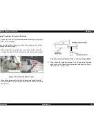
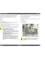
Figure 4-57. Installing the Right Upper Paper Guide Assy.
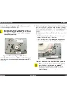
Figure 4-58. Check the Right edge of the Paper Eject Roller
C A U T I O N
n
Do not bend or damage the Loop Scale for PF Encoder
Sensor during disassembly and assembly.
n
Do not touch the surface of the PF roller by hand.
n
Be careful not to scratch the PF roller assembly during
disassembly and assembly, since its surface is specially
coated to improve paper feeding.
n
Be careful not damage the hook during disassembly and
assembly of the Paper Guide Front.
n
Be careful not damage the fixing hook portion on the
Bushing 12. It is very fragile parts.
n
Do not touch teeth of the Gear 76 on the left edge of PF
Roller. This parts is High Accuracy Gear. Refer to Figure
4-55.
C H E C K
P O I N T
n
When the Right Upper Paper Guide Assy,. is set on the Top
Frame with the Torsion Spring 117.6, make sure that PE
sensor lever is set in the square hole on the Right Upper
Paper Guide. Insert the Right Upper Paper Guide from the
front setting the PE Sensor Lever in the square hole in the
Right Upper Paper Guide Refer to Figure 4-57.
n
Make sure that the Torsion Spring 117.6 is set in the gutter
on the Upper Paper Guide Assembly.
n
Make sure the PF Earth Spring is set in the gutter at the left
edge of the PF Roller.
n
When the Loop Scale for PF Encoder Sensor and Gear 76
were replaced with a new one, you have to assemble the
those parts by using the Special tool. Refer to the Chapter 5
(Section 5.3)
n
Make sure that all parts is assembled on the right edge of
the Paper Eject Roller Assy. Refer to Figure 4-58.
Back Side View of the
Printer Mechanism
Torsion Spring 117.6
Right Upper Paper
Guide Assy.
PE Sensor Lever
Gear 8.4
CR Lock Lever
The tip of the CR lock should be set under the
protrusion of Middle Frame
Tension Spring
Pump Planetary Lever
Pump Planetary
Lever Fixing Guide
Gear 10.8
Summary of Contents for Stylus Color 760
Page 1: ...EPSONStylusCOLOR760 Color ink jet printer SEIJ99004 SERVICE MANUAL ...
Page 8: ...C H A P T E R PRODUCTDESCRIPTION ...
Page 27: ...C H A P T E R OPERATINGPRINCIPLES ...
Page 53: ...C H A P T E R TROUBLESHOOTING ...
Page 72: ...C H A P T E R DISASSEMBLYANDASSEMBLY ...
Page 109: ...C H A P T E R ADJUSTMENT ...
Page 142: ...C H A P T E R MAINTENANCE ...
Page 152: ...APPENDIX C H A P T E R ...


