Summary
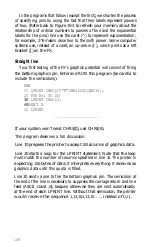
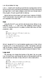
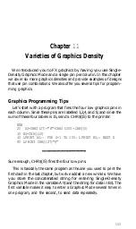
You enter Graphics Mode with the
C H R $ ( 2 7 ) “ K ”
CHR$(n
1
) CHR$(n
2
) command. You determine the number of graphics
columns by filling the two reservation slots, n
1
and n
2
. You fire your
pin patterns by adding up the pin labels, which consist of powers of
two.
Here is the command we introduced in this chapter:
CHR$(27)“K”CHR$(n
1
)CHR$(n
2
);
Enters Single-Density Graphics Mode and spe-
cifies width setting. Width = n,+256*n,
where n
1
is 0 - 255 and n
2
is 0 - 7 on the FX-80
and 0 -
12
on the
FX-100
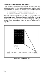
Note: Single-Density graphics dots are printed 60 per inch horizon-
tally and 72 per inch vertically.
142
Summary of Contents for FX-80
Page 1: ......
Page 22: ......
Page 23: ......
Page 26: ......
Page 31: ...Figure 1 1 The FX 80 and FX 100 printers 14 ...
Page 32: ...Figure 1 2 Printer parts 1 5 ...
Page 38: ...Figure 1 8 DIP switch vent 21 ...
Page 42: ...Figure 1 11 Ribbon insertion 25 ...
Page 51: ...Figure 1 20 Paper thickness adjustment 34 ...
Page 85: ......
Page 92: ......
Page 95: ......
Page 97: ...80 ...
Page 109: ......
Page 117: ...Figure 7 3 Staggering STAIR STEPS 100 ...
Page 119: ...Table 7 1 Line spacing commands 102 ...
Page 129: ...112 ...
Page 147: ...130 ...
Page 181: ...Figure 12 4 Corner of the FX 80 design ...
Page 189: ...Figure 12 10 Most distinct version Figure 12 11 Reversed version 172 ...
Page 215: ...198 ...
Page 231: ...214 ...
Page 249: ......
Page 269: ......
Page 272: ...iv ...
Page 283: ......
Page 290: ......
Page 305: ...282 ...
Page 311: ...288 ...
Page 323: ...300 ...
Page 339: ......
Page 343: ...320 ...
Page 349: ...326 ...
Page 353: ...330 ...
Page 354: ...Schematic 331 ...

