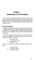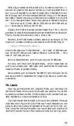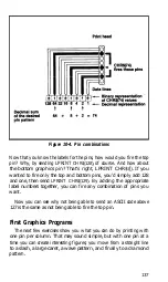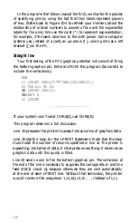
Each pass of the print head contains one piece of the total pattern,
which can be as tall or short as you desire. You don’t have to use the
whole page or even an entire line for your graphics figures. In fact,
you can reserve as little or as much space as you like for a figure-and
position it anywhere on the page.
Graphics Mode
Multi-line figures are printed in lines that are either seven or eight
rows tall. For each graphics figure, you must first enter one of the
seven versions of Graphics Mode and then tell the printer the number
of columns you wish to print on each line. In other words, you specify
the density of the dots.
Here is the format for entering Single-Density Graphics Mode (60
dots per inch).
LPRINT CHR$(27)"K"CHR$(n
1
)CHR$(n
2
);
The two number slots (n, and n
2
) determine the number of columns
reserved for graphics.
Why two numbers instead of one? To get around a limitation of the
BASIC CHR$ function, which with only one reservation slot would
not let you print a figure across the entire width of the page. An 8-inch
page can hold up to
480
Single-Density graphics dots per row. But
since the BASIC CHR$ function is limited to numbers from 0 to
255,
you can’t send a number as large as 480 directly to the printer.
That’s where the second number slot fits in. You use the two sets of
numbers together to send large numbers to the printer. The first num-
ber that you specify (n1) indicates a number of columns
(0-255),
as
you’d expect. A
255
in that position says “reserve
255
columns for
graphics,” which means that any Single-Density figure less than half a
page wide can be handled easily by the first number alone. Although
you may sometimes need only this first slot for specifying width, you
must not stop with that specification. You must still satisfy the printer,
which always expects a value for the second slot (n
2
). Send it a
0.
134
Summary of Contents for FX-80
Page 1: ......
Page 22: ......
Page 23: ......
Page 26: ......
Page 31: ...Figure 1 1 The FX 80 and FX 100 printers 14 ...
Page 32: ...Figure 1 2 Printer parts 1 5 ...
Page 38: ...Figure 1 8 DIP switch vent 21 ...
Page 42: ...Figure 1 11 Ribbon insertion 25 ...
Page 51: ...Figure 1 20 Paper thickness adjustment 34 ...
Page 85: ......
Page 92: ......
Page 95: ......
Page 97: ...80 ...
Page 109: ......
Page 117: ...Figure 7 3 Staggering STAIR STEPS 100 ...
Page 119: ...Table 7 1 Line spacing commands 102 ...
Page 129: ...112 ...
Page 147: ...130 ...
Page 181: ...Figure 12 4 Corner of the FX 80 design ...
Page 189: ...Figure 12 10 Most distinct version Figure 12 11 Reversed version 172 ...
Page 215: ...198 ...
Page 231: ...214 ...
Page 249: ......
Page 269: ......
Page 272: ...iv ...
Page 283: ......
Page 290: ......
Page 305: ...282 ...
Page 311: ...288 ...
Page 323: ...300 ...
Page 339: ......
Page 343: ...320 ...
Page 349: ...326 ...
Page 353: ...330 ...
Page 354: ...Schematic 331 ...


