background image


Document number: ED. 03622.00.001.R04.ENG                                                                   

Page 113 of 151


ED.02518.00.001.R08.ENG


        Page 113


)


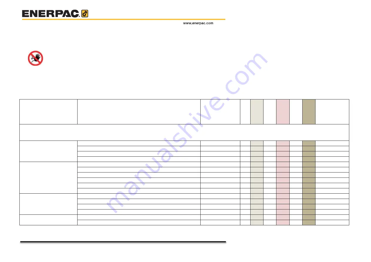
Enerpac strongly advises to apply parts as bought from Enerpac.


Hazard


Applying parts which to not apply to the specifications may cause 

hazards to 

personnel

 and the system 

 
Perform maintenance on the mechanical part according to the list as shown below. 
Record all activities in Appendix E 

 Recording maintenance

”.


For hydraulic fluid safety information sheet, see Appendix J 

Hydraulic fluid safety information

”.


    Subject 

   Action 

Person 

O (Owner)


EE (Enerpac expert)


First 

40 hours


8 hours


Daily


40 hours


Weekl

y


500 ho

urs


yearly


2000 h

o

urs


2 years


10000

 hours


10 ye

ars


Remarks


1.  Electro motor, tank and cooler 


1.1. Motor 

Check on oil leakage, damages and paint work 

O


Check if the bolts are still tightened 

O


Check on damages 


Wipe it clean and free from dust 


1.2. Hydraulic tank 

Check on oil leakage, damages and paint work 


Check if the bolts are still tightened 


Replace all seals 

EE 


Replace the level gauges 

EE 


Drain the tank (water and sludge) 

EE 


Exchange the filler cap (which contains a filter) 


1.3. Valves 

Check on oil leakage and damages 

O


Check if the bolts are still tightened 

O


Replace all seals 

EE 


Check all valve settings 


1.4. Manifolds 

Check on oil leakage and damages 


Check if the bolts are still tightened 


Summary of Contents for SBL1100

Page 1: ...struction and Maintenance Manual Super Boom Lift Document Number ED 03622 00 001 R03 ENG Status Final Original instructions SBL1100 SBL900 1068 915 metric ton hydraulic portal lift system www enerpac com ...

Page 2: ...lic oil Shell Add safety data sheets for all other prescribed lubricants Kroon oil 19 July 2017 D Rosier R Broenink On request of Ruben Bosman minimum operating temperature set to 10 degrees 03 Changed the extending time during lifting and added the retracting time during lowering of the load New front page Remote control explanation arrows Editorial changes Safety data sheet HF95 hydraulic oil Ad...

Page 3: ...act that this manual has been drafted with great care we cannot guarantee that it does not contain any errors x The use and interpretation of all information in this manual and the possible consequences through improper use of the system are wholly the responsibility of the user Enerpac shall under no circumstances accept any responsibility for such improper use Pictures and illustrations in this ...

Page 4: ...__________________________________________ 16 2 3 Symbols applied to the System __________________________________________________ 17 2 4 Welding work ________________________________________________________________ 19 2 5 Working on the electrical system_________________________________________________ 19 2 6 Working on the hydraulic system ________________________________________________ 19 2 7 ...

Page 5: ...____________________________________ 81 7 Execute a lifting operation ___________________________________________________ 87 7 1 Risks and Warnings____________________________________________________________ 87 7 2 Warning signs on the System ____________________________________________________ 88 7 3 Suspend the load _____________________________________________________________ 89 7 4 Lift the lo...

Page 6: ...ce ____________________________________________________ 130 F Drawings for the skid tracks _________________________________________________ 133 G Drawing of the units _______________________________________________________ 135 H Drawings of the side shift units ______________________________________________ 137 I Drawings of the lifting lug __________________________________________________ 139 J...

Page 7: ...enced documents Ref Name Identification Manufacturer 1 Operation of electrical installations Low voltage NEN 3140 NEN 2 Operation of electrical installations NEN EN 50110 1 NEN 3 General rules and safety requirements for systems and their components NEN EN ISO 4413 NEN 4 USB stick Wind calculations Enerpac 5 Technical handbook Enerpac 6 EC Declaration of conformity Enerpac 7 ASME B30 1 2015 Jacks ...

Page 8: ...ine s intended use The user shall bear any and all risks The definition of intended use also includes strict compliance with the instructions in the user manual and assumes that the equipment is inspected and maintained at the indicated times x The System should only be used in the intended manner as described in the instructions in this manual in particular listed in section 3 3 System configurat...

Page 9: ...ith all applicable rules and regulations x Assembly and disassembly may only be performed by trained installers under the supervision of an authorized person who has adequate knowledge of the System The responsibilities are conform the standard as referred to in Ref 7 ASME B30 1 2015 x In some situations the owner and the user may be the same entity and is therefore accountable for all of the foll...

Page 10: ...the following 1 access for the system and associated equipment 2 sufficient room to assemble and disassemble the system 3 an operating area that is suitable for the system with respect to levelness surface conditions support capability proximity to power lines excavations slopes underground utilities subsurface construction and obstructions to operation 4 traffic control as necessary to restrict u...

Page 11: ...ration the system Operator shall stop the system functions in a controlled manner System operations shall resume only after safety concerns have been addressed and the continuation of the operation is directed by the system Director The system Operator s responsibilities shall include the following a reviewing the requirements for the system with the Director before the operations b knowing what t...

Page 12: ...wever the system Operator shall obey a stop signal at all times no matter who gives it u understanding bask load rigging procedures For responsibility of rigging the load and ensuring that the load is rigged properly v if power fails during the operations x set all locking devices x move all power controls to the OFF or neutral position x secure and stabilize the load if practical w before leaving...

Page 13: ... Clasp hands in front of body INDIVIDUAL LEGS Hold up one finger for leg marked 1 two fingers for leg marked 2 Regular signals follow 1 9 Lifetime No lifetime of the System is specified since its safe and effective lifetime strongly depends on x the intensity of the use x the quality of the maintenance x the service conditions in which the System is applied like wet or salty environments x and the...

Page 14: ...te the most common used labels in industrial documents NB NB is used to highlight important work activities and for additional information Caution Caution is used if failure to heed the given instructions may result in damage to the system Attention General warning to the operator of potential damage to equipment and the environment Hazard Draws the user s attention to potential hazards to personn...

Page 15: ... and followed 2 1 Mandatory protective gear While using the System ensure that the applicable safety regulations are observed Make sure that all people on the working place observe the following safety regulations Always wear safety goggles and a safety helmet Always wear safety footwear Wear safety gloves But we strongly advise not to wear them when operating handheld control consoles Wear a safe...

Page 16: ...tem before leaving it unattended x Use all required Personal Protection Equipment PPE x Do not wear any loose clothing or jewelry Long hair must be tied back x Tools and equipment necessary for dis assembly of the System as well as for maintenance has to be in good condition Badly maintained equipment can cause time wastage and lead to permanent damage to the equipment and or it surroundings x Kee...

Page 17: ...directions The table below show the most common used warning symbols Danger of contact with moving machine parts Danger Lethal voltage in the control panels Danger of parts of hands getting trapped caught Danger of parts of feet getting trapped caught Danger of falling Danger Exercise extreme attention and caution when under moving loads Danger of getting trapped caught between moving parts ...

Page 18: ... Wear safety glasses to prevent eye injuries Wear safety shoes to prevent injuries caused by falling objects and or feet getting caught in machinery Wear hearing protection Wear a safety helmet to prevent injuries caused by falling objects Wear a safety harness The stickers on the machine are official documents and it is not permitted to alter them or render them illegible It is strictly obligator...

Page 19: ...hine to earth Insulate any adjacent components that are still receiving power x Check and inspect the electrical system of the System at regular intervals Problems such as loose connections and damaged or stuck wiring must be resolved immediately Only use original fuses and circuit breakers with the correct current value x If work does need to be performed on components receiving power then cordon...

Page 20: ...st aid procedures are required in cases of accidents with chemicals But in cases of small quantities standard measures suffice rinse thoroughly with water wash with soap provide fresh air remove any contaminated clothing In common the following rules are applicable x Contact with the skin o rinse thoroughly with water o remove any contaminated clothing o wash the relevant body parts with soap x Co...

Page 21: ... the entrance in order to provide assistance in the event of an emergency x You are legally required to be familiar with the potential hazards of the product The safety information sheets are intended to provide adequate correct and up to date information on all substances used on the worksite x Relevant safety information sheets are given in Appendix J Hydraulic fluid safety information of this m...

Page 22: ... penetration Do not eat drink or smoke when using this product May cause hypersensitivity of the airways or heritable mutations in male reproductive cells is a potential carcinogen and or is toxic to human reproduction Apply a strict hygiene health policy and wear suitable personal protection equipment Explosion hazard when heated and or in presence of sparks Keep away from heat sparks open flames...

Page 23: ...ed to these components will be under mechanical tension If you release these parts they could change position suddenly and injure you seriously 2 10 Transport loading and unloading of the System x Loading and unloading has to be performed by properly trained operators x Only use lifting and hoisting equipment with suitable capacity for the loads in question x Lift loads as described in the user ma...

Page 24: ...NG Page 24 of 151 ED 02518 00 001 R08 ENG Page 24 3 System Overview This chapter describes the main functions and components of the System 3 1 General Remote control console RCC Skid track Unit Boom Header beam Side Shift unit Lifting lug ...

Page 25: ...m is provided with on board hydraulic power No hydraulic hoses have to be used on the working scene Only connecting electric power is required 3 1 1 The Unit x The units can be controlled o Individually using the control panel on the electrical cabinets o Individually and simultaneously by the remote control console RCC x The tilting cylinders can put the boom in upright position x In order to syn...

Page 26: ...e boom o enable smooth moving of the stages into each other The guiding pads are adjustable in order to centralise the stages precisely Since the guiding pads are made of plastic material they are subject to wear x In order to synchronise the lifting heights of all units each unit is provided with a stroke sensor The sensor is provided with a wire which is attached to the top of the boom x Each un...

Page 27: ...erefore the skid tracks are provided with a ridge on top 3 1 3 The Header beam The header beams across the top of the units create a portal Two types of header beams can be applied x Integral header beams of various lengths x Modular header beams composed out of more sections to construct various lengths Header beams of foreign make may be applied if x they have equal material properties x their f...

Page 28: ... Side shift units enable moving of the load in transversal direction Therefore each side shift unit is provided with an electro motor which propels rollers The rollers run on the header beams x Side shift units have only one single speed x Side shifts units can be controlled o by the RCC o by the control panel on the electrical cabinet x Optionally a transportation frame may be delivered for trans...

Page 29: ... lugs cannot move the load aside Depending on the mass of the load to be lifted you can apply lifting lugs x in double plate configuration x in single plate configuration 3 1 6 The Remote control console RCC The RCC enables the operator x to control the system on a safe distance x to control all units simultaneously and synchronised The RCC can be connected to the system x by radio x by wire ...

Page 30: ...of the machine 10 C The battery of the RCC will only have half capacity Maximum operating temperature of the machine 50 C Minimum storage temperature of the machine 25 C Maximum storage temperature of the machine 60 C Minimum storage temperature of the RCC x 20 C x 0 C While charging the battery Maximum storage temperature of the RCC x 60 C x 45 C While charging the battery Noise pressure Measured...

Page 31: ... a load Approx 60 minutes Retracting time 20 Hz during lowering a load Approx 28 minutes Side shift HBS3000 90 cm minute HBS6000 Mk1 90 cm minute Bearing capacities of units side shifts lifting lugs and beams Unit SBL900 Stage 1 700 kN 5060 mm 8372 mm Stage 2 500 kN 8372 mm 11360 mm SBL1100 Stage 1 2621 kN 4409 mm 7060 mm Stage 2 1689 kN 7060 mm 9724 mm Stage 3 945 kN 9724 mm 12016 mm Side shift H...

Page 32: ...Drawings for the skid tracks Units Appendix G Drawing of the units Side shift Appendix H Drawings of the side shift unit Lifting lugs Appendix I Drawings of the lifting lug For technical details of the header beams reference is made to Ref 5 Technical handbook The weights of the main parts of the system Type Weight kg Unit 11950 incl oil Side shift unit HBS3000 814 kg HBS6000 MK 1 1544 kg Lifting ...

Page 33: ...ity x Configuration with a single longitudinal header beam x Configuration with double longitudinal header beams x If you want to use other configurations than the depicted make sure the correct calculations are made Enerpac may advise x Enerpac cannot be held responsible for application of other configurations than the proposed x Configurations in which non Enerpac equipment such as strand jacks ...

Page 34: ... applied to both the SBL1100 and the SBL900 systems 3 3 3 Position of the load x The System can lift loads while the load is suspended from the header beams x The System can tilt a load x If you want to put the load on top of the header beams contact Enerpac x The system is exclusively suitable for lifting with four booms Call Enerpac for advice when you want to position the load differently ...

Page 35: ...ansporting people Attention Lifting operations with less than four units is strictly prohibited Hazard Lifting a load with only two units is a high risk operation hazardous and therefore prohibited The System with its load can tip over completely due to x out of centre of gravity x swinging of the load x large sling angles Such an operation may lead to an accident which causes damage to the x mach...

Page 36: ...e load x Dimensions of the load x Allowable ground bearing pressure 3 Determine the lifting height 4 Consider the following subjects x Lifting capacity of the most heavily loaded unit x Lifting capacity of the side shift x Lifting capacity of the header beams x Bearing capacity of the ground Is additional foundation underneath the skid tracks necessary x The wind load It is of the utmost importanc...

Page 37: ...ring pressure Use is made of the effect that pressure spreads down in an angle of 450 as shown below So the higher the foundation the lower the ground bearing pressure The following sections describe how the bearing pressure can be calculated Feel free to apply your own calculation methods The pressure on the ground is inverse proportional with the height of the supporting material side view Found...

Page 38: ...tric tons Skid track Height Skid height 0 3 m Width Skid width 0 3 m Auxiliary material beams shackles etc Aux mass 20 metric tons Safety factor S 1 7 Maximum force on one unit which can occur during the operation F t b s 1 Bearing surface including the spreading effect in length direction of one unit Bearing_surface 2 tracks Unit length 2 Skid height Skid width 2 Pressure on the ground metric ton...

Page 39: ...ecklist in appendix A Checklist for planning a lifting operation with the calculated bearing pressure Attention the exerted ground pressure may never exceed the maximum allowed ground bearing pressure Example Load to be lifted 1068 metric tons Ground pressure 7 1 0 2 4 20 12 4 1068 V 241 metric tons m2 ...

Page 40: ...oundation material Steel plates have to be mounted between the timbers and the skid tracks The dimensions of the bearing surface are determined as follows x The width of one footprint x The length of one footprint Width Skid width 2 Timber height Timber height Skid width Unit length Skid height Timber height Length Unit length 2 Skid height Timber height ...

Page 41: ...rce on one unit which can occur during the operation F Depends on the operation Timbers Width Timber width Depend on the applied timbers Height Timber height Gap between the timbers Timber gap 1 Surface of one footprint width length Skid width 2 Timber height Unit length 2 Skid height Timber height 2 Surface on which the pressure is exerted for one unit 2 footprint 2 footprint 3 Support ratio to c...

Page 42: ...ssure may never exceed the bearing capacity of the ground Example Load to be lifted 1068 metric tons Timbers Width 0 10 m Height 0 10 m Gap 0 03 m Measure of one footprint Width Skid width 2 Timber height 0 3 2 0 1 0 5 Length Unit length 2 Skid height Timber height 2 76 2 0 3 0 1 3 56 m L W 0 5 3 56 1 78 m2 Two footprints 2 1 78 3 56 m2 Support ratio 0 10 0 10 0 03 0 77 Ground pressure 7 1 77 0 56...

Page 43: ...30N mm preferably Azobé wood Steel plates Steel length Smin Steel width Timber width Steel thickness 15 mm mechanical compressive strength 30 N mm without occurrence of deflection Mounting properly secured x Wood is a natural product its quality is not assured In order to guarantee quality test the timbers on 125 of the expected load x For your planning keep in mind that suitable wood may not alwa...

Page 44: ... consciously during lifting operations these parameters may interfere with each other in a negative way Test situations differ from real life situations 4 2 1 Maximum load The bearing capacity of the System depends on the degree of extension of the beams the more extension the less bearing capacity will be Complete the checklist in Appendix A Checklist for planning a lifting operation under Stage ...

Page 45: ...increased significantly and exceeds 250 kN The system is loaded to its limits but none of the units is overloaded The green unit is overloaded The system cannot lift the 1000 kN anymore but less to prevent overload in the green unit The capacity of the system has decreased due to eccentricity of the load The more the COG of the load deviates from the centre of the System the less the capacity will...

Page 46: ...Document number ED 03622 00 001 R04 ENG Page 46 of 151 ED 02518 00 001 R08 ENG Page 46 Capacity chart of SBL1100 metric version ED 03622 70 001 R00 ENG ...

Page 47: ...Document number ED 03622 00 001 R04 ENG Page 47 of 151 ED 02518 00 001 R08 ENG Page 47 Capacity chart SBL900 metric version ED 03454 70 001 R00 ENG ...

Page 48: ... units x Check the capacity of the side shift units using the information in section 3 2 2 Operational specifications x Enter the load in the checklist given in Appendix A Checklist for planning a lifting operation 4 3 2 Lifting lugs If there is no need to move the load in transverse direction then simple lifting lugs can be applied rather than the more complicated side shift units x Choose single...

Page 49: ...apacity charts For the capacity charts of Enerpac header beams reference is made to Ref 5 Technical handbook Distance between the anchor points Allowable load Example how to determine the allowable load of the header beam for two anchor points Loads within the green area are allowed The distance between the anchor points is 1250 1250 mm so the maximum allowable load is 520 kN per anchor point Exam...

Page 50: ...ce between the top of the capacity chart and the curve is 900 300 600 3 The allowable load is 300 600 2 600 Enter the allowable load on the header beam in the checklist given in Appendix A Checklist for planning a lifting operation Caution The force on each anchor point shall not increase the capacity of the header beam x Earlier purchased Enerpac Hydrospex header beams may be applied if their cap...

Page 51: ...mitted side load on the System is 1 5 of the actual load Enter the max expected side load Appendix A Checklist for planning a lifting operation The side load caused by wind depends on x the size of the object x the wind speed x the height of the header beams lifting height To calculate the permissible wind speed you may apply the provided calculation program see Ref 4 USB stick Wind calculations T...

Page 52: ...hatsoever lifting operations may be carried out when the wind speed is exceeds the permissible values x When lifting assume a worst case scenario Wind is unpredictable and may quickly change speed and direction Example of a completed form Load Properties Operational parameters Load width Load length Load height Load weight 4 5 3 1250 m m m kN Total lifting height Sling length 7 0 0 5 m m Header ge...

Page 53: ...products are applied 5 1 How to hoist parts of the System 5 1 1 Hoisting units Pre conditions for moving a unit x no header beams are mounted x no load is attached x the boom is in horizontal position The units can be moved in two ways A Using a forklift truck Use the fork holes of the unit In order to prevent damage to the wheels of the units x keep the bottom of the unit at a height of at least ...

Page 54: ...t in vertical position 5 1 2 Hoisting the Skid tracks The skid tracks can be hoisted x by a forklift truck Use the fork holes x by a crane Use the two lifting eyes 5 1 3 Hoisting the header beams Header beams are provided with lifting eyes Lifting eyes Fork holes 8m header beams only Lifting eyes Fork holes ...

Page 55: ...are given for the HBS6000 only but are valid for the HBS3000 as well The side shift units shall only be hoisted using the lifting eyes When not in use then put the side shift units down horizontally Put them on timbers Optionally transportation frames may be delivered for transporting and storage Lifting eye eyes for strapping down Forklift hole Adjustable height Forklift hole Locking pin ...

Page 56: ... the strap down eyes Remove those straps 3 Remove the locking pin 4 Store the locking pin in one of the pipes 5 For HBS6000 remove the locking plates 6 Hoist the side shift unit out of the transportation frame Use all four lifting eyes For storing the side shift units in the transportation units proceed in reverse order Pay attention to the following x The height of the transportation frame is adj...

Page 57: ...has to be performed with utmost care as it is the system s primary safety issue The foundation of the Skid tracks is the exclusive responsibility of the user 5 2 1 Build the foundation For building the foundation proceed as follows Install the foundation material as you determined see section 4 1 Ground bearing pressure calculation Regard the following aspects x If the diameter of the timbers is n...

Page 58: ... in place proceed as follows Put the skid tracks on the foundation and mount them together Regard the following aspects x Put steel plates between the timbers and the skid tracks x Make sure no slack is left between the foundation and the skid tracks Eventually use shims x Put foundation material directly underneath the couplings of the skid tracks ...

Page 59: ...age 59 5 2 3 Align the skid tracks Align the Skid tracks according to the following requirements Nr Alignment requirement Tolerance 1 The skid tracks shall be in parallel 13 mm top view 2 The skid tracks shall be aligned from the start to the end 12 mm top view Front view Side view ...

Page 60: ...ve now skew 0 25 front view of one skid track 4 The skid tracks shall not incline 0 2 side view of one skid track 5 The skid tracks shall be flat 8 mm over 3 meter side view of one skid track 6 The surfaces of the segments of the skid tracks shall be well aligned Use shims if necessary side view of one skid track ...

Page 61: ...rd the hoisting instructions as given in paragraph 5 1 1 Hoisting units x Put all units with the electro cabinet towards the outside x The grooves in the roller tracks have to match with the ridges on the skid tracks 2 Set the moving direction of all units in such a way that they travel in the same direction Use 5 on the control panel see section 6 2 1 The switches and indicators Do this after the...

Page 62: ... since the units feature automatic phase detection This assures the correct rotation direction of the electro motors There are two options for connecting the units x connect each unit individually to the main power x connect the units two by two to the main power The two power sockets of a unit are functional equal both can be used for power input and power output Do not interconnect more than two...

Page 63: ...power Attention Never put the boom in upright position or lower it x when something is attached to it The tilting cylinders are not designed to bear additional weight x while the boom is extended The unit might tumble due to the different centre of gravity Proceed as follows 1 Remove the three lifting shafts from the frame x Remove the spring clips from the three shafts x Pull the three indicated ...

Page 64: ...ENG Page 64 2 Check x nobody is close to the unit x no cables can be pinched x nothing is attached to the boom 3 Use the buttons on the control panel to raise the boom see section 6 2 The Control Panel of the unit The tilting cylinders extend The boom gets in upright position ...

Page 65: ...lay with the buttons on the control panel for fine positioning to enable restoring of the shafts Hazard A missing shaft may result in an unstable unit foot and thus also an unstable system 5 Decompress the tilting cylinders by retracting them slightly using the buttons on the control panel Keep an eye on the pressure gauge there should not be pressure built up ...

Page 66: ...beams 5 7 1 Assemble the modular beam When you apply the modular header beam then construct it as follows 1 Put two sections male female together and align the holes 2 Mount the connection bolt 3 Mount the flanges of the connection bolt 4 Tighten the bolts according to the table in Appendix 0 Torque settings ...

Page 67: ...of the swivel 4 Clamp the header beam to the swivel using the distance strips and the locking strips Note that two types of beams can be mounted x Wide 480 mm x Narrow 300 mm Set the locking strips of the swivel according to the applied type 5 Level the beam Use 1 of the control panel see page79 6 Tighten the bolts according to the table in Appendix 0 Torque settings x Make sure that all bolts are...

Page 68: ...1 Mount the cable guiding wheel at the header beam 2 Hoist the side shift unit out of the transportation frame Both types of side shift units are depicted Remove the locking pins 3 Put the side shift on the header beam Preferably put the side shift units with their chain boxes at the same side of the header beam This makes setting of the running direction of the side shift units more logical ...

Page 69: ...ent number ED 03622 00 001 R04 ENG Page 69 of 151 ED 02518 00 001 R08 ENG Page 69 4 Place the anchor block 5 Lock the bolts with the locking pins 6 When you re going to apply slings then mount the sling tool ...

Page 70: ...ch a way that it cannot get pinched 8 Mount the other side shift similarly 9 Set the moving direction in such a way that side shift units will move in the same direction Use 5 on the control panel see section 6 2 1 The switches and indicators This may be done in a later phase when the units have been provided with electric power e q section 7 7 Move the load in transversal direction ...

Page 71: ...der beam configurations Enerpac provides a solution for mounting longitudinal beams Contact Enerpac if you want to apply longitudinal beams 5 10 Check the stroke sensor Though the wire of the stroke sensor is not a removable part its presence and the correct mounting has to be checked due to its vulnerability Proceed as follows 1 Verify that the wire is connected to the strip on top of the boom 2 ...

Page 72: ...e out The disturbance may be caused by radio reflections or dead area s Walking to another position may help Connection fail measures x If the communication fails for 2 seconds then all movements of the units and the side shifts are stopped x If the communication fails for 10 seconds then the system makes an Emergency stop For recovering from this situation reference is made to section 6 1 The Eme...

Page 73: ...ata cable to one of the units Each units are provided with two RS485 sockets Use one of them the sockets are functionally identical 5 Connect another data cable to the other socket of the unit and connect it to the next unit 6 Carry on connecting until all units are connected The sequence in which you interconnect the units does not matter since the units will identify themselves automatically 7 P...

Page 74: ...ot so The system will automatically detect their presence 2 Ensure that the Emergency stop button on the RCC is in the non activated position 3 Switch the main power switches on the control panels of all units to on The power on indicator on the control panel of the Units will be lit 4 Make sure that the Emergency stop buttons on all units are in the non activated position The blue indicator shoul...

Page 75: ...7 Switch the same switches to off again 8 Switch the RCC off and on As soon as the communication is established x the text Engine still is displayed x an asterisk is displayed If the RCC detected data cables then the wireless means are switched off Now it is possible to control the units ...

Page 76: ...nfiguration initially The setting is persistent and remains after switching off the power Only when the RCC or one of the units was replaced reprogramming is required Reprogramming has to be performed for each unit individually Proceed as follows 1 Make sure the battery of the RCC is charged 2 Switch the units off 3 Use the switches to deselect all units 4 Switch the unit which has to be programme...

Page 77: ...he RCC and the unit are connected 8 Eventually repeat 2 7 for the other units 9 Verify that the number on the RCC match with the numbers on the units by travelling with the units individually 5 12 Perform an all over visual inspection of the System Inspect the System visually Enter the result of the inspection in the checklist given in Appendix B Checklist for installing the System ...

Page 78: ... the unit is in Remote Control then other units which are in Remote Control too are switched off as well To recover the system from an Emergency situation o investigate why the button was pressed o turn and pull the emergency button o press the blue button x On the RCC When the button is pressed o all units which are in remote control are switched off To recover the system from an Emergency situat...

Page 79: ... not move 6 Switch the unit to remote control the unit is controlled by RCC or to local control the unit is controlled by the buttons on this cabinet 7 It lit when the power is connected 8 It lit when failure of the motor 9 It lit when a motor of a side shift fails All side shift motors stop 10 Is lit when any emergency button of one of the connected units was pressed Press to reset the emergency ...

Page 80: ...ions of the unit and the side shift For Local Control proceed as follows 1 Switch the unit on use 14 and 13 Verify that 7 is lit and 8 and 9 are dimmed 2 Use 6 to enable Local Control In local control the following operations can be executed x Set the positive running direction of the unit use 5 x Set the positive running direction of the Side Shift use 5 x Extend or lower the boom use 1 x Travel ...

Page 81: ...ol all units simultaneously Let s call this mode Remote control Applying the RCC ensures that x the moving speeds of the units is synchronized x the heights of the booms during a lift operation are kept equal within a tolerance of 24 mm The RCC cannot control the tilting cylinders used for putting the boom in upright position System start up is faster when the RCC is switched on before the units a...

Page 82: ...sed to charge the batteries 1 Display load per lifting foot lifting height per foot error messages 3 Emergency stop When pressed all Units which are in Remote are switched off The Units have to be reactivated using their own Control Panels 5 Switch Power of the console 6 Switch Driving speed of the Units fast slow 7 Switch lift or lower the load 8 Switch Move Unit 9 Switch move Side Shift 10 Butto...

Page 83: ... in Paragraph 8 2 List of problems and solutions under Reports on the display of the Intellilift Console When communication with the Units is OK an asterisk is shown behind the Lift value x The display is provided with background lighting In order to extend the battery life the background lighting is switched off if no changes are detected for a period of 15 seconds x Emergency pressed The report ...

Page 84: ...but only when that unit was on Remote control Reference is made to section 6 1 The Emergency buttons x Battery level The display shows the power level of the battery The console can operate approximately 8 hours on a fully charged battery Switch the console off after use and connect it with the 12V loader Only apply the delivered loader ...

Page 85: ...ration is not part of the daily routine Proceed as follows 1 Preconditions x RCC switched off x Units switched off 2 Set Speed on the RCC to the hare high speed 3 Press Zero lift and keep it pressed while you switch the console on Keep Zero lift pressed until the message System not ready is shown 4 Release the Zero lift button The RCC is now in calibration mode The Calibration mode message appears...

Page 86: ...m position 9 Deselect the unit The stroke sensor has been calibrated The message Calibration succeeded is shown 10 Switch the RCC off 11 Switch the RCC on 12 Verify the displayed position It should be the maximum position 13 Retract the cylinder to the very minimum position 14 Verify the displayed position It should be approx 0 ...

Page 87: ...ication is restored x Signals to the operator should be in accordance with the standards prescribed in section 1 8 6 Hand signals If special signals are required they shall be agreed upon by the operator and support personnel prior to the lifting operation Signals shall be discernible or audible at all times No action shall be taken unless signs are clearly understood x Load handling personnel sha...

Page 88: ...tem without question Hazard Despite all inherent safe design measures safeguarding and complementary protective measures there will always be the residual risk of tumbling of the system 7 2 Warning signs on the System The following signs are applied to the system The legend of the symbols is given in section 2 3 Symbols applied to the System ...

Page 89: ...y endanger the stability of the System front view 2 Keep the lifting straps as short as possible Hazard long slings may enable swinging of the load causing dangerous lateral forces front view 3 The header beam has to be kept level at any time with a tolerance of 0 2 Level the header beam at installation time During operation the header beam is kept level automatically front view 4 Lifting slings h...

Page 90: ... the form given in Appendix D Recording a lifting operation 2 Verify that the checklists given in a Appendix A Checklist for planning a lifting operation b Appendix B Checklist for installing the System c Appendix C Final checks are completed and signed off 3 Switch the RCC on The RCC starts up The software version number is displayed 4 Verify the battery of the RCC is fully charged The battery st...

Page 91: ... a bandwidth of 24 mm o When the height of one cylinder differs more than 12 mm from the others its lifting speed or the lifting speeds of the other beams is slowed down until all heights are within a bandwidth of 6 mm o When the difference of height exceeds 24 mm then system stops moving the load Technical investigations of the problem have to be made Follow the main problem solving procedure as ...

Page 92: ...Verify that all checklists have been completed and signed off x Appendix A Checklist for planning a lifting operation x Appendix B Checklist for installing the System x Appendix C Final checks 3 Verify the power status of the battery of the RCC 4 Select the travelling speed 6 Select tortoise if the system is carrying a load If the system detects a load or the cylinders are extended for more than t...

Page 93: ...e following procedure can be applied to synchronise the positions of the units 1 The units are in rectangular formation if x B1 B2 x A1 A2 To measure the positions of the units you might apply x a tape measure x optical measuring means if you want to stay away from the System while it is bearing a load Feel free to apply your own measuring methods 2 If you detect misalignment then move the concern...

Page 94: ... side shifts simultaneously proceed as follows 1 Apply the RCC 2 Verify that all checklists have been completed and signed off x Appendix A Checklist for planning a lifting operation x Appendix B Checklist for installing the System x Appendix C Final checks 3 Verify the power status of the battery F see the figure below 4 Enable all units use the buttons 4 Ram select 5 Use 9 side shift to move the...

Page 95: ...lateral forces x Always apply four units x Only move two units at a time The other two units are kept passive In the illustration above the red unit is the active one it moves towards the blue unit The blue unit is passive and stands still Hazard This operation has an increased risk of dangerous lateral forces If you want to perform a tilting operation first contact Enerpac An illustrative video o...

Page 96: ... passive units on the RCC 5 Manoeuvre the header beam of the units attached to the future bottom of the load right above the load 6 Attach the bottom of the load to the header beam 7 De select the passive units on the RCC 8 Select the two active units on the RCC 9 Manoeuvre the header beam of the active units right upon the future top of the load 10 Attach the header beam to the load 11 Extend the...

Page 97: ...e the problem 1 Verify that no Emergency button is activated x Is indicator 10 on the control panel lit Emergency active 2 Is there an overload problem x Check the displayed Loads on the RCC E see page 82 x Check the heights displayed on the RCC A D see 82 3 Is there a technical problem in one of the units Check the Control Panel of all units see page 79 x indicator 7 should be lit power on x indi...

Page 98: ...RCC Battery is low Charge the battery for at least 4 hours Reports on the display of the RCC Emergency pressed An Emergency button was pressed either on one of the unit or on the RCC Reset the emergency Communication timeout Radio disturbed Use cable connection visible behind the RAMs No problem Appears when the cable connection is used System not ready Initiation message Wait a 20 seconds Stroke ...

Page 99: ...flow or leakage Contact Enerpac The Side Shift does not move Side shift not connected Connect the Side Shift Thermic safety relays has tripped Open the Electrical Cabinet and reset the relays indicated with 10QF2 See the picture below If not successful then Contact Enerpac Indicator Invertor Failure on the Electrical Cabinet is lit Try to start the motor use 4 If not successful the open the Electr...

Page 100: ...rder keep electrical and other moisture sensitive components dry The tarpaulin is not included in the delivery but can be added as an option x Long term storage For long term storage a dry and closed space is recommended Make sure the electrics are kept dry Pay special attention to x the stroke sensor and the x travelling distance measuring device since they are vulnerable parts Travelling distanc...

Page 101: ...ave to be performed The intervals are based on regular use of the System which is approximately one lifting operation per month When the System is intensively or less intensively used the maintenance intervals will change accordingly x Only perform maintenance on the units if they are not under load x Only perform maintenance on the units if no header beams are mounted x Maintenance which is not d...

Page 102: ...nd damages O x Check all bolts O x Visual check of the lifting lugs O x Inspect the readability of the warning signs Clean if obscured by dirt Restore if damaged or even no longer present O x 1 2 Test the oil of the gearboxes Test the oil of the gearboxes see section 10 1 5 Replace the oil of the gearbox O x 1 3 Replace the oil of the gearboxes Test the oil of the gearboxes see section 10 1 5 Repl...

Page 103: ...r chain see section 10 1 3 Tension the roller chains O x 3 Side shift unit 3 1 Lubricate the chain Lubricate the chain see section10 1 4 Lubricate the side shift units O x 4 Booms guiding pads 4 1 Adjust the guiding pads Adjust the guiding pads See section ࣛ ཧ ཧ ඖࡀぢࡘ ࡾࡲࡏࢇࠋ O EE x x 4 2 Booms Lubricate the booms on the running surface of the guide pads with synthetic motor oil for instance 10W40 Se...

Page 104: ... lubricate the chains proceed as follows 1 Make sure the power supply has been switched of 2 Unlock the front doors and open them 3 Visually inspect the chains and the gears 4 Clean the chains 5 Lubricate the chain with Kroon Oil multi purpose grease 3 6 Close the front doors and lock them 7 Verify that the wheel of the travelling distance measuring device runs fine doors chains ...

Page 105: ...te shaft are affixed to the frame of the unit with 6 bolts which can move in slotted holes 2 Loosen the bolts of the shaft 3 Tension the lower chain The slack in the middle of the chain shall be 10 mm Use hand power 4 Tighten the bolts of the shaft 5 Loosen the bolts of the gearbox 6 Tension the upper chain until the slack is 10 mm in the middle of the chain Use hand power 7 Tighten the bolts of t...

Page 106: ... Use lawful hoisting and lifting equipment 1 Make sure the power supply has been switched of 2 Lift the unit 3 Verify the slack between the upside of the middle roller and the frame of the unit If the clearance exceedes 10 mm then continue with the next steps 4 Unscrew the four bolts 1 at the rear side of the unit so the side of the stairs both at the left and the right hand side of the track So e...

Page 107: ...e Caution Tensioning the chain too tight might harm the driving mechanism 6 Tighten the bolts 7 Inspect the roller chain x Check he bolts on damage x Make sure the bolts of the chain are tightened 45 Nm 10 1 4 Lubricate the side shift units Clean the chains of the side shift units and lubricate them Use Kroon Oil multi purpose grease 3 This is valid for both types of side shift units The bearings ...

Page 108: ... of the gearbox 1 Perform a purity test on the oil of the gearboxes 2 Change the oil of the gearbox x If the yearly purity test points out or x at least every 10 years Use 2 6 litres of oil type ISO VG 320 Mineral oil 10 1 6 Lubricate the swivel 1 Lubricate the nipples of the swivel two at both sides Gear boxes ...

Page 109: ... boom is provided with four sets of steel plates on which guiding pads are mounted One set of steel plates consists of a two plates which abut against each other x Two guiding pads are mounted on the inner plate one on the top and one on the bottom x The distance between the inner and the outer plate can be adjusted by adjusting bolts Those bolts can be reached through holes in the boom x The plat...

Page 110: ...rning them clockwise Turn them as far as possible 4 Turn only a half turn counter clockwise 1 the two upper bolts of side one 2 the two upper bolts of side two 3 the two upper bolts of side three 4 the two upper bolts of side four Use little force Turn the bolts simultaneously Therefore two persons are required 5 Repeat step 4 until 100 Nm is reached 6 Turn only a half turn counter clockwise 1 the...

Page 111: ...hetic motor oil for instance 10W40 Remarks x In case of vibration of the booms during operation execute this procedure also x In case of contamination of the running surface s by for instance sand clean the running surfaces and lubricate the booms again In case of new guiding pads execute this procedure also But before installing the new pads make sure to activate the pads by rubbing them with a r...

Page 112: ...s the following is present a excessively worn scored cracked bent or broken ram b cracked or broken jack housing or cylinder c internal or external hydraulic fluid leak d damaged seals or valves e excessive pitting or corrosion f excessive nicks or gouges g missing or illegible identification h indications of structural damage due to heat or evidence of unauthorized welding i improperly functionin...

Page 113: ...ily 40 hours Weekly 500 hours yearly 2000 hours 2 years 10000 hours 10 years Remarks 1 Electro motor tank and cooler 1 1 Motor Check on oil leakage damages and paint work O x Check if the bolts are still tightened O x x Check on damages x Wipe it clean and free from dust x 1 2 Hydraulic tank Check on oil leakage damages and paint work O x Check if the bolts are still tightened O x x Replace all se...

Page 114: ...ned O x x Replace motor pump coupling EE x 1 9 Cooler Check on oil leakage and damages O x Check if the bolts are still tightened O x x Clean the cooler O x Measure pressure difference delta p at the cooler EE x 2 Hydraulic connections 2 1 Pipes hoses and brackets Check on oil leakage and damages O x Check if the couplings are tightened well O x x Replace all seals within the piping Waldform EE x ...

Page 115: ... damages and paint O x Check if the bolts are still tightened O x x Replace all seals door seals and inspection hatches EE x Grease the hinges and locks O x Replace engine feet EE x 4 Cylinders 4 1 Common Check on leakages O x Check if the bolts are still tightened O x x Replace all seals EE x Grease the bearings EE x ...

Page 116: ...to be performed The minimum requirement is that the purity of the medium is in accordance with class 7 of NAS 1638 Proceed as follows 1 Ensure that the cylinder is completely pulled in 2 Disconnect the hose from to the ball valve 3 Connect your own hose to the ball valve 4 Drain the oil While draining keep an eye on the oil level gauches 5 Attention Dispose the oil responsibly ...

Page 117: ...he filter element The return filter cleans the oil that flows back into the tank Due to contamination of the oil the permeability of the filter will decrease which causes a raise of the pressure of the return flow of the oil The pressure is shown on the clogging indicator x Green the pressure is 0 2 bar The filter is fine x Yellow the pressure is 2 3 bar The filter is still working but has to be r...

Page 118: ... the filter element proceed as follows 1 Unscrew the return filter cap 2 Remove the internal filter element 3 Put a new filter element To ensure correct operation only replace with an element with equal brand and type Use Hydac return filters The exact type is listed on the parts list of the machine ...

Page 119: ...rst 40 hours 8 hours Daily 40 hours Weekly Each 500 hours Each year 2000 hours Every 2 years 10000 hours Every 10 year Remarks 1 Electro motor 1 1 General Check on damages O x Wipe it clean and free from dust O x x 2 Cables and connectors 2 1 General Check on damages O x 3 Devices and cabinets 3 1 General Check on damages O x x Check if the bolts and nuts are still tightened O x x Replace all seal...

Page 120: ...he end of its lifetime proceed as follows x Drain and collect the hydraulic oil and other fluids separately if applicable x Remove the batteries x Remove the electric components and electric wiring x Remove the metal components Separate all metals and liquids for recycling purposes and bring it to a recycling company Attention Dispose all material in a responsive way ...

Page 121: ...56 cylinder 26 83 86 91 96 115 116 cylinders 25 48 63 64 65 81 82 83 85 86 87 91 92 99 D damage 8 14 16 19 22 23 35 53 87 107 damaged 19 102 124 125 129 damages 102 112 113 114 118 129 130 131 dangerous 89 95 99 deflections 33 deleterious 8 device 19 25 26 93 98 100 104 dimensions 27 38 40 44 52 direction 8 25 28 30 31 38 48 52 61 62 68 70 80 87 91 92 93 94 122 123 draining 115 driving 98 99 102 1...

Page 122: ...7 110 125 149 permeability 116 permissible 51 52 122 persistent 76 person 9 87 personal 21 22 planning 36 39 42 43 44 48 50 51 52 90 92 94 96 122 123 plywood 43 preparation 53 87 prepare 36 87 pressure 19 22 27 30 36 37 38 39 41 42 65 113 116 122 130 pressurized 19 protection 21 22 23 protective 15 22 R radio 29 72 railway 27 recycling 119 S safe 13 19 29 81 safety 3 7 8 14 15 16 19 20 21 57 87 99...

Page 123: ...pacity Mass of the load Lifting height mm Stage of Extension 1 2 Capacity in highest stage kN Allowable load kN The mass of the load does not exceed the allowable load Minimum force per unit is sufficient kN Maximum force per anchor point does not exceed the capacity of the side shift if applicable kN The force on the applied header beam does not exceed the limits Maximum permissible wind speed X ...

Page 124: ... tracks aligned according to instructions in manual 5 Units Move all units forwards and backwards over a short distance using the RCC to ensure you have set the positive driving direction correctly Slide all beams in and out over a short distance This assures the communication functions properly Check the battery status of the RCC The stroke sensors are undamaged 6 Header beam Bolts on the swivel ...

Page 125: ...nspection of the hydraulic components no oil leakages Running surfaces of the skid tracks are clean Dirt may cause the units slip The units can run freely and are not obstructed Inspection of the electrics electrical cables are undamaged electrical cables cannot be pinched 9 Applied equipment What Length Capacity Mass Lifting straps Chains Other 10 Commitment Installed by Date Signature Approved b...

Page 126: ...d and signed off 3 Inspect the System No parts of the portal lift are damaged No leakages of the hydraulic components Drop zone is cordoned off No people are inside the unsafe zone Barriers and tape are used Running surfaces of the skid tracks are clean The units can run freely and are not obstructed The weight of the load is indicated on the RCC correctly The side load does not exceed 1 5 of the ...

Page 127: ...heck the suspension of the load The anchors on the header beam are in line with the hoisting points of the load front view The lifting straps are short front view The header beam are level front view Lifting slings are plumb side view 5 Commitment Inspected by Date Signature Approved by Date Signature ...

Page 128: ... 00 001 R08 ENG Page 128 D Recording a lifting operation 1 Project Project Customer Location Date 2 Recording of activities Activity Time The checklists have been completed and are signed off Appendix C Final checks has been completed and signed off 1 2 3 4 5 6 7 8 ...

Page 129: ...ocument number ED 03622 00 001 R04 ENG Page 129 of 151 ED 02518 00 001 R08 ENG Page 129 Part 2 3 Activity Time 9 10 11 12 13 15 16 17 18 3 Commitment Executed by Date Signature Approved by Date Signature ...

Page 130: ...ck all bolts Visual check of the lifting lugs Inspect the readability of the warning signs Clean if obscured by dirt Restore if damaged or even no longer present 1 2 Test the oil of the gearboxes Test the oil of the gearboxes 1 3 Replace the oil of the gearboxes Replace the oil of the gearboxes 1 4 Adjust the guiding pads Adjust the guiding pads 2 Chain of the units 2 1 Lubricate the chain Lubrica...

Page 131: ... analyze Replace the hydraulic oil Check the oil level 1 6 Hydraulic filter Replace the filter element Replace the seals of the filter housing 1 7 Breathers Replace the breather 1 8 Bellhousing Check on damages Check if the bolts are still tightened Replace motor pump coupling 1 9 Cooler Check on oil leakage and damages Check if the bolts are still tightened Clean the cooler Measure pressure diffe...

Page 132: ...eet 4 Cylinders 4 1 Common Check on leakages Check if the bolts are still tightened Replace all seals Grease the bearings Subject Action Person Date 1 Electro motor 1 1 General Check on damages Wipe it clean and free from dust 2 Cables and connectors 2 1 General Check on damages 3 Devices and cabinets 3 1 General Check on damages Check if the bolts and nuts are still tightened Replace all seals 3 ...

Page 133: ...Document number ED 03622 00 001 R04 ENG Page 133 of 151 ED 02518 00 001 R08 ENG Page 133 F Drawings for the skid tracks ...

Page 134: ...Document number ED 03622 00 001 R04 ENG Page 134 of 151 ED 02518 00 001 R08 ENG Page 134 ...

Page 135: ...Document number ED 03622 00 001 R04 ENG Page 135 of 151 ED 02518 00 001 R08 ENG Page 135 G Drawing of the units ...

Page 136: ...Document number ED 03622 00 001 R04 ENG Page 136 of 151 ED 02518 00 001 R08 ENG Page 136 ...

Page 137: ...Document number ED 03622 00 001 R04 ENG Page 137 of 151 ED 02518 00 001 R08 ENG Page 137 H Drawings of the side shift units ...

Page 138: ...Document number ED 03622 00 001 R04 ENG Page 138 of 151 ED 02518 00 001 R08 ENG Page 138 ...

Page 139: ...Document number ED 03622 00 001 R04 ENG Page 139 of 151 ED 02518 00 001 R08 ENG Page 139 I Drawings of the lifting lug ...

Page 140: ...Document number ED 03622 00 001 R04 ENG Page 140 of 151 ED 02518 00 001 R08 ENG Page 140 J Hydraulic fluid safety information ...

Page 141: ...Document number ED 03622 00 001 R04 ENG Page 141 of 151 ED 02518 00 001 R08 ENG Page 141 ...

Page 142: ...Document number ED 03622 00 001 R04 ENG Page 142 of 151 ED 02518 00 001 R08 ENG Page 142 ...

Page 143: ...Document number ED 03622 00 001 R04 ENG Page 143 of 151 ED 02518 00 001 R08 ENG Page 143 ...

Page 144: ...Document number ED 03622 00 001 R04 ENG Page 144 of 151 ED 02518 00 001 R08 ENG Page 144 K Kroon Oil Multi purpose grease 3 ...

Page 145: ...Document number ED 03622 00 001 R04 ENG Page 145 of 151 ED 02518 00 001 R08 ENG Page 145 ...

Page 146: ...Document number ED 03622 00 001 R04 ENG Page 146 of 151 ED 02518 00 001 R08 ENG Page 146 ...

Page 147: ...Document number ED 03622 00 001 R04 ENG Page 147 of 151 ED 02518 00 001 R08 ENG Page 147 ...

Page 148: ...Document number ED 03622 00 001 R04 ENG Page 148 of 151 ED 02518 00 001 R08 ENG Page 148 ...

Page 149: ...Document number ED 03622 00 001 R04 ENG Page 149 of 151 ED 02518 00 001 R08 ENG Page 149 ...

Page 150: ...ch Nm Fine pitch Nm Nominal size Strength class Copper grease Copper grease 0 08 0 08 M4 8 8 2 2 10 9 3 2 12 9 3 8 M5 8 8 4 3 10 9 6 3 12 9 7 4 M6 8 8 7 4 10 9 10 9 12 9 12 5 M7 8 8 12 0 10 9 17 5 12 9 20 5 M8 8 8 18 19 10 9 26 28 12 9 31 32 M10 8 8 36 37 10 9 52 55 12 9 61 64 M12 8 8 61 63 10 9 90 93 12 9 105 109 M14 8 8 97 103 10 9 145 150 12 9 165 175 M16 8 8 145 155 10 9 215 225 12 9 250 270 M...

Page 151: ...s Copper grease Copper grease 0 08 0 08 10 9 570 610 12 9 670 710 M24 8 8 510 640 10 9 730 900 12 9 850 1060 M27 8 8 750 920 10 9 1070 1310 12 9 1250 1530 M30 8 8 1000 1280 10 9 1450 1820 12 9 1700 2130 M33 8 8 1400 1700 10 9 1950 2430 12 9 2300 2840 M36 8 8 1750 2230 10 9 2500 3170 12 9 3000 3710 M39 8 8 2300 2850 10 9 3300 4050 12 9 3800 4740 ...

Reviews: