


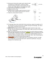


13. Using a pair of pliers and a towel, gently clamp the stem
of the Nozzle (a small spinner is loosely contained
inside the Nozzle) and spin (counter-clockwise) the cap
from the stem. *Skip steps13-17 if installing new nozzle.
14. Clean all the parts with parts washing fluid.
15. Replace the stem o-ring.
16. Holding the stem vertically, place the spinner on top of
the stem. Then, thread the nozzle Cap onto the stem.
17. Tighten the nozzle Cap to the stem.
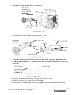
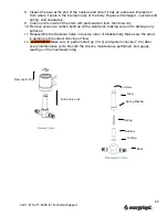
18. The passage through the nozzle block for the nozzle has a plug at the opposite end of
the nozzle which must be removed for complete cleaning of the Passage - use thread
sealer during reinstallation (refer to figure).
19.
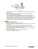
IMPORTANT!
—Being careful not to apply parts washer fluid to the heater wiring
harness, clean the nozzle passage of the Nozzle Block. Make sure parts are clean and
dry prior to reassembly.
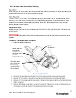
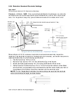
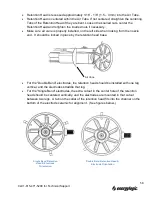
20. Refer to the following section (8.5.6) for Flame Retention Head and Electrode Settings
and reassemble the Nozzle Line Assembly.
Be sure to re-install the air vane
(shown in figure) in the proper location – opposite side of bulkhead fitting). Failure to
install this component properly will result in an off-center flame, which may damage the
heat exchanger and void the heat exchanger warranty.
21.
Make sure to perform start up (7.4.2) and system checks (7.4.3) after
every maintenance cycle. Record the checks, maintenance performed, and gauge
readings in the maintenance log.
Disassemble Nozzle
Passage Plug
Plug
Nozzle
Cap
Spinner
Stem
O-Ring
Air Vane
56
Call 1-615-471-5290 for Technical Support
Summary of Contents for EL-140H
Page 2: ......
Page 51: ...45 Call 1 615 471 5290 for Technical Support ...
Page 90: ...10 2 Carlin 50200E Primary Control 84 Call 1 615 471 5290 for Technical Support ...
Page 91: ...85 Call 1 615 471 5290 for Technical Support ...
Page 93: ...87 Call 1 615 471 5290 for Technical Support ...
Page 94: ...88 Call 1 615 471 5290 for Technical Support ...
Page 95: ...89 Call 1 615 471 5290 for Technical Support ...