


Quick Start Guide
- 4 -
Quick Start Guide
Before you begin, be sure to review this document in full for important information regarding
sized for the intended installation. Be sure to reference and be familiar with local code and
municipal FOG Program requirements. The Authority Having Jurisdiction (AHJ) can be your
best friend and your worst enemy.
1. Prepare your
installation area
to accommodate the interceptor and ensure safe
section of this document (See Page 8-10).
3. Select preferred outlet connection
Side connection is accessed by removal of the caps supplied, that cap then being
used to seal the end outlet.
lower in and level interceptor accounting for anticipated surface
Note: For installations where high ground water is anticipated
,
once located pour at least 8” of concrete on top of your prepared
Remove all packaging including the skid. Locate the interceptor so as to allow for accessibility
surface ensuring tank is equally supported.
XL100/ XL150 Approx. 2150lbs [975kg])
A minimum safety factor of 2 shall be applied in calculation/design.
Concrete Anchor
Base (if anchoring
is required)
Min.
6"
Inle
O
t
utlet
Min.
12"
Min.
12"
Min.
8"
6" Minimum Base
of Crushed aggregate
material approximately
3/4" size rock, pea
gravel or sand
Ensure adequate room for
piping connections
and inspections
G
E
T
NI
E
S
A
E
R
P
E
C
R
T
R
O
T
NI
E
S
A
E
R
G
C
R
E
R
O
T
P
E
G
E
T
NI
E
S
A
E
R
P
E
C
R
T
R
O
C
R
E
T
NI
E
S
A
E
R
G
R
O
T
P
E
OUT
SIDE -
SIDE - OUT
END - OUT
IN
Max. 25ft
(for PDI)
PDI
External Flow
Control installation
Cleanout
Cleanout
F
CD
Air
I
n
tak
e
Sink
Inlet
Outlet
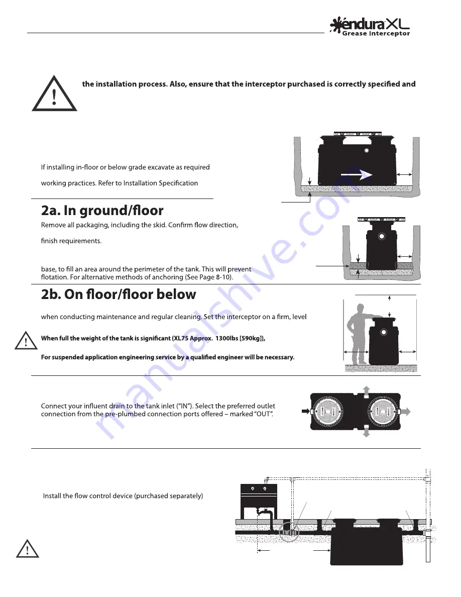
4. Installations with External Flow Control
(PDI G-101/ASME A112.14.3 - Type A)
See page 6 for
cleanout part numbers
Min. Base
Anchoring
(if required)
Level end to end
Flow Direction
Level side to side
For PDI G-101/ASME A112.14.3 (External Flow Control)–
upstream, after the last branch connection discharging to the
interceptor. A maximum of 25ft from last branch discharge
to the entry of the interceptor is required to meet published
recommendations. See Page 12 for connection formats.
Plumbing code typically requires provision of a cleanout
to grade immediately before and after the inlet and outlet
connections.


