assembly into the front of the pool as shown on the video taking
care to keep the hose ends from getting wet. Two people can
accomplish this if they work carefully in stages. Be careful not
to catch the liner. Carefully slide the assembly all the way to the
front of the pool and make sure it is centered left to right.
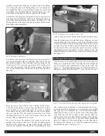
Peel off all of the protective white plastic from the stainless steel
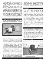
side benches and install them inside the pool using the side sup-
ports at the junction between two benches. See Figure 32.1. On
the two benches at the rear of the pool include the Rear Left and
Rear Right corner assemblies.
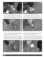
Peel off all of the protective white plastic from the stainless steel
rear bench assembly with the perforated grill. Attach the rear
base middle support to the perforated rear base using the two
stainless steel 10/32 screws on top and one 10/32 stainless steel
screw and nut provided with this plastic support. See Figure
32.2. Lower this assembly into the rear of the pool as shown on
the video.
Keep all screws loose until you have started all the screws.
Focus first on the bottom screws as they are difficult to work on
once the holes are covered with water. If you use a cordless
screw gun as shown on the video take care not to over tighten
the screw into the PVC. Be careful to inspect for burrs while
installing these screws. If a burr occurs remove the screw and
discard. We have supplied extra screws.
Do not try to install the stainless steel corner covers or any
optional corner steps at this time. They may fit tightly against
the liner in the corners and you risk cutting the liner. Put them
aside for the moment. They should not be installed until more
water is in the pool which will push the liner back in the corners.
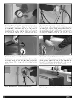
Once the stainless steel is in and the holes are lining up, you may
continue filling the pool while you work. Stop filling three inch-
es below the lowest thru-wall connection. Once all the screws
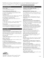
are tight, secure the front housing with the grab bar back against
the steel wall of the pool using the special corrosion resistant
self-drilling fasteners provided. Use only stainless steel, self
drilling fasteners provided. Do not use Tek screws which will rust.
See Figure 32.3.
33.Thru-wall Connections
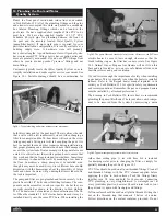
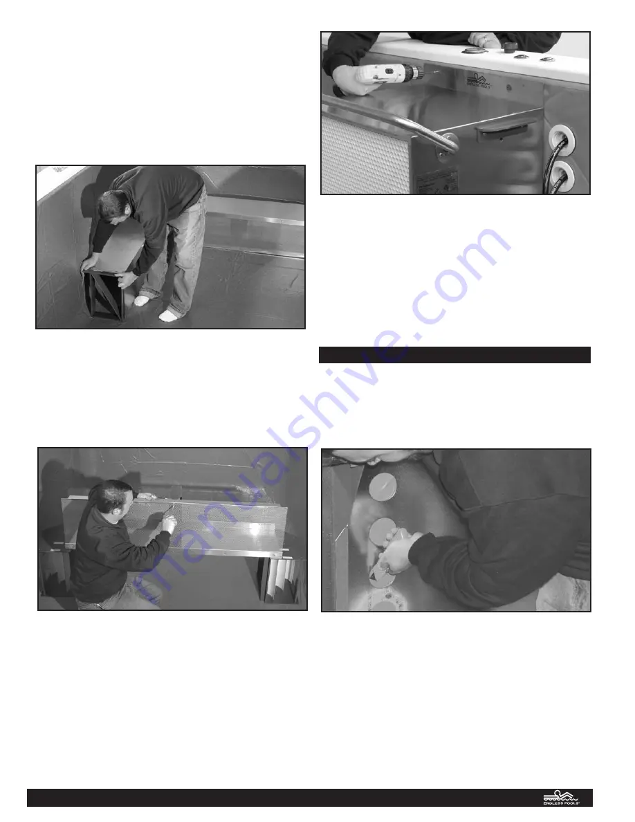
Once the water level is three inches below the lowest thru-wall
fitting, cut 3 round holes in the liner using the holes through the
steel as a template and a utility knife as shown in the video. See
Figure 33.1. If optional hydrotherapy jets (Tech Bulletin #6) or
underwater lights (Tech Bulletin #7) were selected you must
also cut these holes in the liner as well and plumb the jets sys-
tem and/or install the light niches. Located in the same padded
bag with the valve assembly are 2 round thru-wall fittings.
Install both of these as shown on the video. One fitting takes
water from the pool and is under suction and the other one
returns water to the pool after filtering, heating, and purifying.
The suction port is the lowest of the three inline prepunched
holes. See Figure 33.2. The return fitting is on the other side of
the housing (the left side as you face the propulsion assembly
from inside the pool). See Figure 33.3
Fig 32.3: Attaching the front housing to the pool wall.
Fig 32.1: Installing the side supports
Fig 32.2: Attaching the 10/32" screw and nut.
Fig 33.1: Cut the thru-wall holes through the liner using the steel as a template.
18


