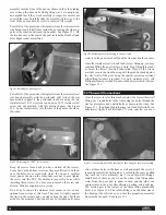
done with the previous thru-wall fittings. See Figure 33.9. Hand
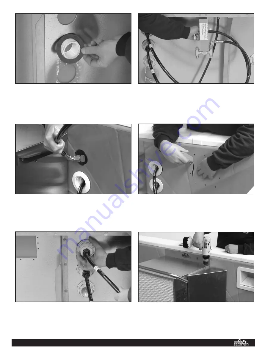
tighten the large hex nut and connect the hydraulic elbow fit-
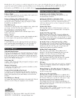
tings to the top of the valve assembly as shown in the drawing
accompanying the valve assembly. See Figures 33.10 and 33.11.
You may continue to fill the pool to a point three inches below
the bottom of the skimmer opening. In the unlikely event that
any of these fittings drips call Customer Service. Do not apply
a wrench to any of these fittings without first calling Customer
Service.
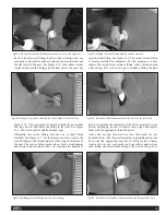
The final opening on the front panel is the rectangular opening for
the skimmer. See Figure 33.12. The skimmer will be plumbed to
the suction fitting as shown in Tech Bulletin #3 in order to reduce
the suction hazard and protect the pump in the event that the sys-
tem is kept on with the water low. The final protection against
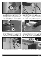
suction hazard is the stainless steel triangular shroud which
installs over these inline fittings at the end of the installation. See
Figure 33.13. Plumb the skimmer as described in the manufac-
turer’s literature in the box. Use the silicone provided.
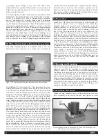
Fig 33.8: A cork gasket is installed between the outside pool wall and the hex nut
Fig 33.9: Run the hydraulic hoses through the pool wall.
Fig 33.10: Hand tighten the hex nut to secure the hydraulic hoses.
Fig 33.11: Attaching the hydraulic hoses to the valve assembly.
Fig 33.12: Cutting the liner using the pool wall as a template.
Fig 33.13: Installing the stainless steel shroud over the hydraulic and suction fittings.
20


