Safety
Information
Introduction
Product
information
System
design
Mechanical
installation
Electrical
installation
Getting
started
Optimisation
Parameters
Technical
data
Component
sizing
Diagnostics
Unidrive SP Regen Installation Guide
35
Issue Number: 2 www.controltechniques.com
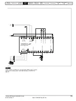
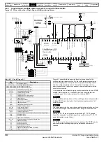
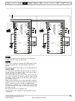
DC bus fusing is required for all motoring drives in a single Regen,
multiple drive system in both the +DC and -DC.
VDR4, VDR5 and VDR6 when operating with a 690Vac supply should
consist of two varistors each in series as detailed in Table 3-24 on
page 28.
See Chapter 10
on page 183 for fuse rating information.
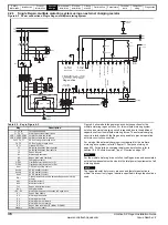
Unidrive SPMC
For a regen system, the SPMC can be used to charge the common DC
bus when the power is first applied, however this will once the regen
system is powered up no longer be required.
The Unidrive SPMC must be supplied with 24Vdc to feed both the fans
and control circuits. This 24Vdc can also be used as a means of starting
and stopping the SPMC rectifier as the SPMC will only fire its thyristors
when the 24Vdc is present.
Fitting a 5A relay interlocked (or a normally closed auxiliary contact) to
the Regen drives main contactor to switch the 24V supply will allow the
SPMC to charge the common DC bus then be disabled (optional).
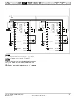
The total amount of capacitance on the common DC bus that the SPMC
can drive is limited due to the inrush current (produced during power up
and during brownouts).
See the following Table for the capacitance limit.
Unidrive SP drive DC bus capacitance levels are available in Table 11-
1 on page 203.
-DC
+DC
F7
F8
UV
W
L1
L2
L3
PE
-D
C
+
DC
21
1
2
3
4
5
6
7
8
9
10
11
41
42
2
2
23
24
25
26
2
7
2
8
2
9
30
31
T.30
T.24
S5
Mt.1
AC
S
u
pp
ly
C
onne
ctions
NO
T
U
S
E
D
C
onne
ctions
Mo
to
ring
dr
iv
e
D
C
Co
n
nec
tio
ns
U
V
W
PE
S2
S3
S
4
Drive enable
0V common
Drive reset
Run forward
Run reverse
Motor thermistor
0V common
Mot
ori
ng dri
ve
F9
F10
UV
W
L1
L2
L3
PE
-D
C
+
DC
21
1
2
3
4
5
6
7
8
9
10
11
41
42
2
2
23
24
25
26
2
7
2
8
2
9
30
31
S5
Mt.2
AC
S
u
pp
ly
C
onne
ctions
NO
T
U
S
E
D
C
onne
ctions
Mo
to
ring
dr
iv
e
D
C
Co
n
nec
tio
ns
U
V
W
PE
S2
S3
S
4
Drive enable
0V common
Drive reset
Run forward
Run reverse
Motor thermistor
0V common
Mot
ori
ng dri
ve
+24V output
+24V output
Mo
to
r
Mo
tor
Drive healthy
Drive healthy
NOTE
NOTE
Summary of Contents for SP1201
Page 219: ......
Page 220: ...0471 0029 02 ...


