Safety
Information
Introduction
Product
information
System
design
Mechanical
installation
Electrical
installation
Getting
started
Optimisation
Parameters
Technical
data
Component
sizing
Diagnostics
Unidrive SP Regen Installation Guide
91
Issue Number: 2 www.controltechniques.com
similar rating coupled together. However, care must be taken to ensure
that the gain is not too high as this can cause excessive ripple in the DC
bus voltage.
8.4 Power factor correction (Pr 4.08)
In regen mode it is possible to produce some current in the x axis of the
reference frame so that the Regen drive can be made to produce or
consume reactive power. Pr
4.08
defines the level of reactive current as
a percentage of the regen drives rated current (Pr
5.07
). Positive
reactive current produces a component of current flowing from the
supply to the drive at the Regen drive terminals that lags the respective
phase voltage, and negative reactive current produces a component of
current that leads the respective voltage. It should be noted that the
maximum current in regen mode is limited to DRIVE_CURRENT_MAX,
and so the drive applies a limit to this parameter
(REGEN_REACTIVE_MAX) to limit the current magnitude. Therefore
the symmetrical current limit (Pr
4.07
) must be reduced below its
maximum value before Pr
4.08
can be increased from zero.
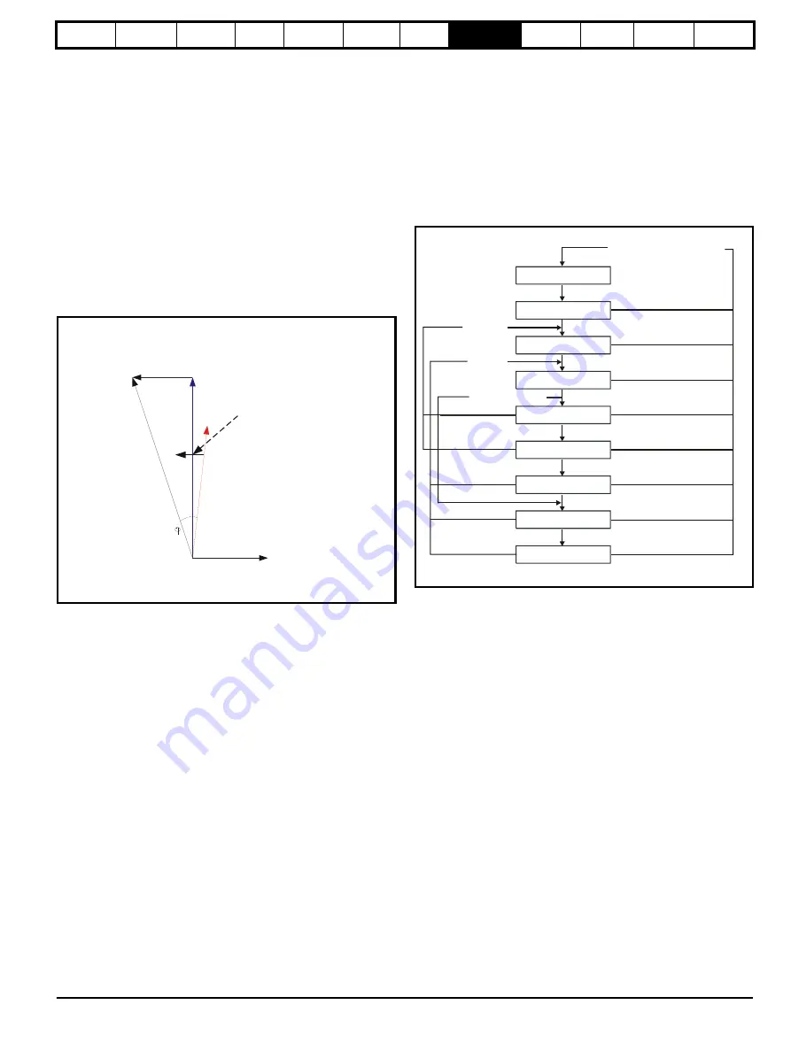
Figure 8-4 Power flow from supply to regen drive
Vs
Supply voltage
Vr
Voltage at regen drive terminals
Ir
Total current at regen drive terminals
JwLIr
Voltage across regen inductor
ϕ
Power factor
8.5 Current trimming
From software V1.10 for Unidrive SP the current trimming can be user
configurable. The default setting for the current trimming in software
V1.10 is as with previous software versions.
The current trimming mode parameter (Pr
3.11
) defines the strategy
used for trimming the current feedback when operating in regen mode
with Unidrive SP.
The two modes that can be selected are as detailed following
Mode 1
- At power up only [Pr
3.11
= 0]
Current trimming is only carried out once after power-up, as
previously available (pre software V1.10) with Unidrive SP Regen.
Mode 2
- At power up and on each enable [Pr
3.11
= 1]
Current trimming is carried out as previously available, once after
power-up, and now in addition it is also carried out before the drive
runs each time it is enabled (software V1.10 onwards) with Unidrive
SP Regen.
Mode 2 (Pr
3.11
= 1) is available to allow the current trimming to be
optimised, and overcome any inaccuracies due to noise / harmonics
from the AC Supply connected to the regen system.
If operating in Mode 2 (Pr
3.11
= 1) the auxiliary contact on the "Regen
drive main contactor" as shown in this installation guide needs to be
moved from T.31 to T.25 to allow the current trimming to be carried out
during each enable. The current trimming only occurs when the main
contactor is open, therefore when the regen drive enable signal is given
with Mode 2 (Pr
3.11
= 1) the main contactor will open and close before
the regen drive becomes active.
Both strategies are shown in the following state machine
Figure 8-5 Current trimming state diagram
Voltage across
regen inductor
Isx
JwLIr
Vs
Vr
Ir
X axis component of
current
Power
factor
Modifying Ir directly
affects power factor
Mains Loss
Current Trim
Close Main Contactor
Waiting for Enable
Open Contactor
Current Trim
Close Main Contactor
Active
(not synchronised)
Synchronied
Disabled
Disabled
Enabled Pr
3
.
11
= 0
Synchronised
Contactor 100ms delay
Trim complete
Contactor open + 100ms delay
Enabled (Pr
3
.
11
= 1)
Contactor 100ms delay
Trim complete
Supply o.k
Mains loss or contactor open
when it should be closed
Summary of Contents for SP1201
Page 219: ......
Page 220: ...0471 0029 02 ...


