


167
User Defined Motors
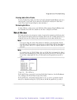
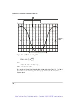
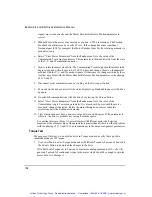
Figure 123:
Oscilloscope Connections
CCW Reference Rotation
Before reading the motor signals, zero the V
TS
oscilloscope channel on a horizontal
graduation marker to allow more accurate readings.
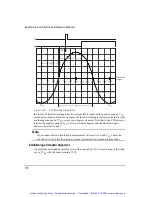
Couple the drill motor to the motor shaft. While spinning the motor counter-clockwise, use
an oscilloscope to examine the phase relationship between encoder channel U and positive
peak of V
TS
(the voltage at motor power terminal T with reference to S).
Use the figure below to determine the electrical angle at which the rising edge of U occurs.
This is the Motor Encoder U Angle. Note that with a CCW reference rotation the positive
peak of V
TS
is at zero electrical degrees and the electrical angle decreases from left to right.
Artisan Technology Group - Quality Instrumentation ... Guaranteed | (888) 88-SOURCE | www.artisantg.com