


Diagnostics Optimization CT MODBUS RTU Technical Data
E300 Design Guide
297
Issue Number: 1
This input bit is used to select the bit 6 speed input when binary or priority speed selection is used,
Control Input mode
(
H11
) = Priority 1 Dir, Binary 1
Dir, Priority 2 Dir or Binary 2 Dir (2, 3, 4 or 5).
In priority input mode this selects
V7 Speed Reference
(
G07
), but in binary input mode it is not used.
When run permit direction input is selected,
Control Input mode
(
H11
) = Analog Run Prmit (0), this input allows the elevator sequencing to start but
the direction is selected from the sign of the analog speed reference i.e. -10 V = CCW, +10 V = CW.
When single direction input is selected,
Control Input mode
(
H11
) = Priority 1 Dir or Binary 1 Dir (2 or 3), and
Direction Input 1 CCW
(
G39
) = Off (0)
clockwise direction is selected, and when
Direction Input 1 CCW
(
G39
) = On (1) counter clockwise direction is selected.
When dual direction input is selected,
Control Input mode
(
H11
) = Analog 2 Dir, Binary 2 Dir or Binary 2 Dir (1,4 or 5), and
Direction Input 1 CCW
(G39) = Off (0) no direction is selected, and when and when
Direction Input 1 CCW
(
G39
) = On (1) counter clockwise direction is selected.
The physical direction of rotation depends on the orientation and wiring of the motor, and the setting of
Direction Input Invert
(
H12
).
If this bit is removed / changed during travel and a digital speed is still selected, a controlled stop will be performed, and the elevator drive will trip
Trip
76
(Dir change)
indicating that the direction signal was changed / removed during travel.
When single direction input is selected,
Control Input mode
(
H11
) = Analog Run Prmit, Priority 1 Dir or Binary 1Dir (0, 2 or 3),
Direction Input 2 CW
(
G40
) is not used and has no effect on the motion profile. Clockwise motion is caused by
Direction Input 1 CCW
(
G39
) = Off (0).
When dual direction input is selected,
Control Input mode
(
H11
) = Analog 2 Dir, Priority 2 Dir or Binary 2 Dir (1, 4 or 5), and
Direction Input 2 CW
(
G40
) = Off (0) no direction is selected, and when
Direction Input 2 CW
(
G40
)
= On (1) clockwise direction is selected.
The physical direction of rotation depends on the orientation and wiring of the motor, and the setting of
Direction Input Invert
(
H12
).
If this bit is removed during travel, and
Control Input mode
(
H11
) = Analog 2 Dir, Priority 2 Dir or Binary 2 Dir (1, 4 or 5), and a digital speed is still
selected, a controlled stop will be performed, and the elevator drive will trip
Trip 76
(Dir change)
indicating that the direction signal was changed /
removed during travel.
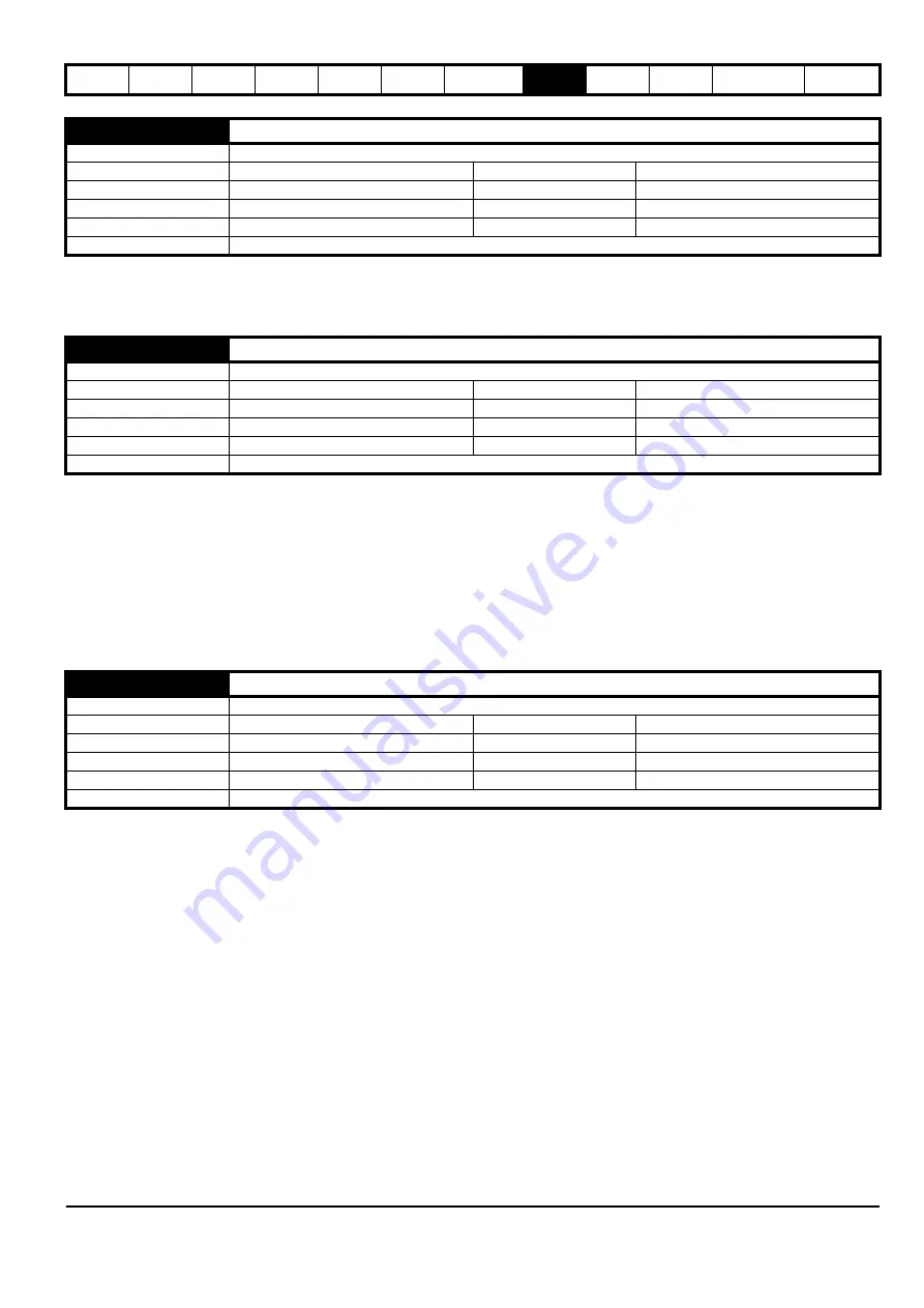
G38
Reference Select Bit 6 Input
Mode
Open-Loop, RFC-A, RFC-S
Minimum
0
Maximum
1
Default
0
Units
Type
1 Bit User Save
Update Rate
4 ms
Display Format
Standard
Decimal Places
0
Coding
RW
G39
Direction Input 1 CCW
Mode
Open-Loop, RFC-A, RFC-S
Minimum
0
Maximum
1
Default
0
Units
Type
1 Bit User Save
Update Rate
4 ms
Display Format
Standard
Decimal Places
0
Coding
RW
G40
Direction Input 2 CW
Mode
Open-Loop, RFC-A, RFC-S
Minimum
0
Maximum
1
Default
0
Units
Type
1 Bit User Save
Update Rate
4 ms
Display Format
Standard
Decimal Places
0
Coding
RW
Summary of Contents for 03200106
Page 490: ...0479 0024 01 ...


