Diagnostics Optimization CT MODBUS RTU Technical Data
E300 Design Guide
155
Issue Number: 1
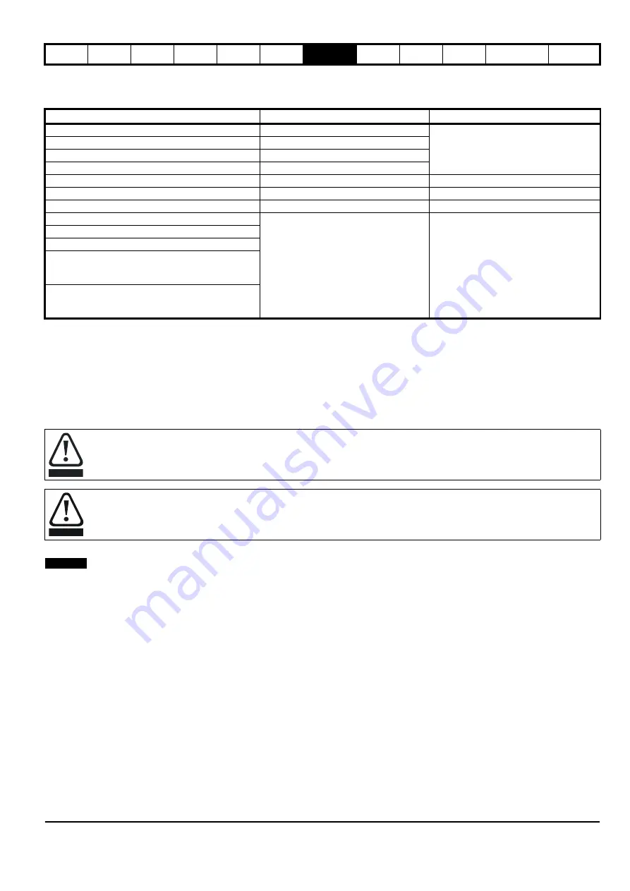
incorrect, the motor will then rotate under control in the wrong direction. Table 7-6 below shows the parameters required for basic RFC-S motor
control and indicates which can be set by the user from the motor nameplate and which can be measured with the static autotune.
Table 7-6 RFC-S static autotune parameters
7.3.2 Rotating Autotune
A26
Motor Autotune
(
B11
) = Rotating autotune (2). The following describes how an autotune can be initiated and normal operation resumed following
successful completion of the test. The autotune should be carried out with no load on the motor, i.e. the ropes should be lifted from the sheave with
the motor free to rotate. Alternatively the Elevator car could be placed in a balanced condition with the counter weight, and with sufficient space to
allow movement of the car during the rotating autotune. During the rotating autotune the motor will rotate, and if the ropes are still attached the car will
also move as follows.
•
Open loop and RFC-A: The motor is accelerated with the selected ramps to
2
/
3
rated frequency and is maintained at that level for up to 40
seconds in the selected direction.
•
RFC-S: The motor will rotate by 2 electrical rev’s i.e. up to 2 mechanical rev’s) in the selected direction.
For RFC-A and RFC-S the position feedback on the motor is also checked during the rotating autotune.
The rotating autotune is carried out with the output motor contactors closed and the motors brake opened during the complete autotune test. The
control over the output motor contactors and the brake during the autotune must be made manually.
The rotating autotune is carried out with the output motor contactors closed and the motors brake opened during the complete autotune test. The
control over the output motor contactors and the brake during the autotune must be made manually.
1. The rotating autotune test cannot be initiated if the drive is tripped
(
L05
) = Off 0) or the drive is active
L06
) = On (1). The
drive can be disabled by removing the drive enable signal from control terminal 31.
2. A rotating autotune test is initiated by setting
A26
(
Motor Autotune
B11
) to Rotating autotune (2)
3. The output motor contactors should be manually closed by an authorised person who is familiar with the requirements for safety, this sequence
also applies the drive enable signal on control terminal 31.
4. The motors brake should be manually opened by an authorised person who is familiar with the requirements for safety.
5. A drive run signal should be applied.
6. The rotating autotune will commence:
Open loop, RFC-A the motor is accelerated to
2
/
3
rated frequency and maintained at this level for up to 40 s in the selected direction
RFC-S the motor will rotate by 2 electrical rev’s (i.e. up to 2 mechanical rev’s) in the selected direction.
Ensure there is sufficient headroom for movement of the lift car if not de-roped as this could result in the car hitting the end stops.
7. If the autotune sequence is completed successfully the drive enable is set to inactive (Inhibit) and
A26
(
Motor Autotune
B11
) is set to zero.
8. The motor brake can be applied.
9. The output motor contactors can be opened.
10. The drive enable will only be set active again by firstly opening the output motor contactors and removing drive enable.
11. If a trip occurs during the autotune sequence, the drive will go into the trip state and
A26
Motor Autotune
B11
) is set to zero, at this point the motor
brake should be applied and the output motor contactors opened.
Parameter
Required for
Detail
A18
(
B02
) Basic
control
Motor nameplate
A22
(
) Slip
compensation
A19
(
) Basic
control
A20
(
Number Of Motor Poles
B05
)
Basic control
A16
(
Position Feedback Phase Angle
C13
)
Basic control with position feedback
Static or rotating autotune
(
B34
)
Basic control
Manually enter, Static or rotating autotune
(
B33
)
Improved performance
Static or rotating autotune
(
B46
)
Basic control
Static or rotating autotune
Current At Maximum Deadtime Compensation
(
B47
)
(
B33
)
Start Current Loop P Gain
(
I03
)
Run Current Loop P Gain
(
I08
)
Stop Current Loop P Gain
(
I13
)
Start Current Loop I Gain
(
I04
)
Run Current Loop I Gain
(
I09
)
Stop Current Loop I Gain
(
I14
)
The rotating autotune will rotate the motor in the direction selected, regardless of the reference. The drive can be stopped at any time during the
autotune by removing the Safe Torque Off (STO), Drive enable or run signal. Following the autotune the Safe Torque Off (STO), Drive enable must
be removed and re-applied before the drive can be made to run the motor.
CAUTION
When a rotating auto tune is being carried out it is the responsibility of the authorized person to ensure they have read the auto tune
instructions and are fully aware of its operation. Also ensure that it is safe to remove (lift) the motors brake with no risk of loss of control.
Ensure during this process there is no load on the motor (or the system is balanced to avoid uncontrolled operation) and there is sufficient
distance for the car to move within the lift shaft when the rotating auto tune is being carried out to avoid the risk of damage to the system.
WARNING
NOTE
Summary of Contents for 03200106
Page 490: ...0479 0024 01 ...


