background image

Guide to diagnostics of electronic controls EWM10931 

2011  SOE/DT-mdm  FCPD-dp  Quality-tb 

50/75 

599 73 77-37


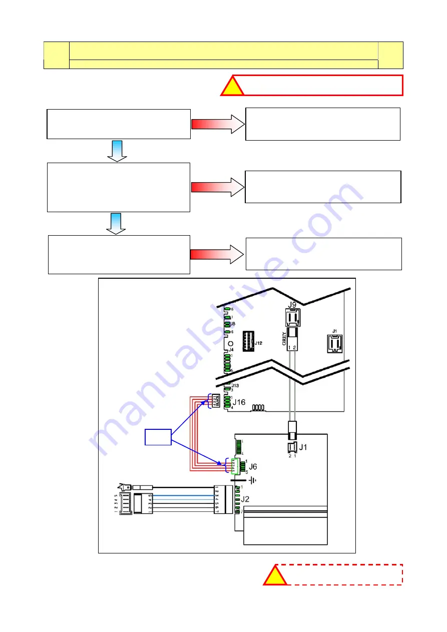
E5d: Data transfer error between Inverter board and main circuit board

E5d 

The lack of communication must last at least 2 sec.  

E5d


Checks to perform: 


Are connectors J16 (main circuit board) 

and J6 (motor control board)  

properly inserted? 

Repair the connectors and repeat the 

diagnostic cycle to check for any  

further alarms.  

Measure the continuity between 

connector J16-1, J16-4 (main circuit 

board) and connector J6-2, J6-5  

(motor control board). 

Is the wiring ok?  

Replace the wiring and repeat the 

diagnostic cycle to check for any  

further alarms. 

Replace the motor control board  

and repeat the diagnostic cycle to  

check for any further alarms. 

Is the appliance working? 

Replace the main circuit board and repeat 

the diagnostic cycle to check for any 

further alarms. 

If there are burns on the circuit  

board, see page 73 

!

check that all the connectors are correctly inserted 

!

NO 

NO 

NO 

MAIN CIRCUIT 

BOARD 

MOTOR CONTROL 

MOTOR 

0


Connector - 

Motor 

Summary of Contents for EWM10931

Page 1: ...TROLUX ITALY S p A Spares Operation Europe Corso Lino Zanussi 30 Publication number I 33080 PORCIA PN ITALY 599 73 77 37 Fax 39 0434 394096 Edition 01 2011 EN Washing machines guide to diagnostics of electronic controls EWM10931 ...

Page 2: ...Guide to diagnostics of electronic controls EWM10931 2011 SOE DT mdm FCPD dp Quality tb 2 75 599 73 77 37 ...

Page 3: ...43 Problems with the component triac controlling the door delay system device with 4 connections 36 E44 Door closed sensing circuit faulty 37 E45 Problems with the sensing circuit of the component triac controlling the door delay system 37 E52 No signal from motor tachometric generator first part 38 E52 No signal from motor tachometric generator second part 40 E57 Inverter is drawing more than 16A...

Page 4: ...cked kinked too high drain filter clogged dirty 67 EF2 Excessive detergent dosing drain hose kinked blocked drain filter dirty clogged 67 EF3 Aqua Control device triggered 67 EF4 Water fill pressure too low and solenoid valve open 67 EF5 Unbalanced load spin phases skipped 67 EF6 Reset appliance 68 EH1 Mains frequency incorrect 68 EH2 Supply voltage too high 68 EH3 Supply voltage too low 69 EH4 ze...

Page 5: ...cteristics 2 thermal fuses so as not to compromise the safety of the appliance It is strictly forbidden to remove exchange the NTC probes from one heating element to another Always empty the appliance of all the water before laying it on its side Never place the appliance on its right side electronic control system side some of the water in the detergent dispenser could leak onto the electrical el...

Page 6: ...WM10931 2011 SOE DT mdm FCPD dp Quality tb 6 75 599 73 77 37 2 WM APPLIANCE CONTROL PANELS These are the stylings available at the time of printing of this Service Manual Others may be developed in future SERIES 7 SERIES 8 NEW COLLECTION SERIES 9 ...

Page 7: ...ately 3 seconds In the first position the operation of the buttons of the related LEDs and of the groups of symbols shown on the LCD screen is checked turn the programme selector dial clockwise to run the diagnostic cycle for the operation of the various components and to read any alarms see diagnostic testing on the following page During this phase if any key combination is pressed except for the...

Page 8: ... flooding level Maximum time 5 mins Water fill to wash compartment Water level in the tub mm 3 Door safety interlock Pre wash solenoid Door closed Water level below anti flooding level Maximum time 5 mins Water fill directly to tub Water level in the tub mm 4 Door safety interlock Solenoid valve pre wash and wash Door closed Water level below anti flooding level Maximum time 5 mins Water fill to c...

Page 9: ...pin Drum speed in rpm 10 10 11 Reading Deleting the last alarm 12 16 The LEDs groups of symbols in the LCD screen and the backlight of the display are turned on in sequence Press a button sensor to turn on the group of icons in the LCD screen or the corresponding LED and the buzzer sounds at the same time Always active User interface functions In most cases this time is sufficient to check the hea...

Page 10: ...equency outside the normal values It is necessary to wait for power supply voltage and or frequency to restore normal conditions The alarms are enabled during the execution of the washing programme With the exception of alarms associated with the configuration and the power supply voltage frequency which are also displayed during the programme selection phase The door can normally be opened except...

Page 11: ... Enter the diagnostic mode para 3 1 Irrespective of the type of PCB and configuration turn the programme selector knob clockwise to the eleventh position the last alarm is displayed To display previous alarms press touch the button sensor to the left of the START PAUSE button in sequence as shown in the figure To return to the last alarm press touch the START PAUSE button sensor SERIES 7 SERIES 8 ...

Page 12: ...the appliance continues to perform the cycle or if you are in the programme selection phase it retains the options selected previously in memory 4 4 Deleting the last alarm It is good practice to cancel the alarms stored After reading the alarm codes to check whether the alarm re occurs during the diagnostic cycle After repairing the appliance to check whether it re occurs during testing Series 7 ...

Page 13: ...til the fifth LED in the right hand row is on 3 Press the START PAUSE button and the nearest option button simultaneously as shown in the figure 4 Hold down the buttons until the hours of operation appear on the display at least 5 seconds 5 2 Display of total operating time This time is displayed with a sequence of two digits at a time the first two digits indicate thousands and hundreds the secon...

Page 14: ...Malfunction in electronic pressure switch circuit Wiring Electronic pressure switch Main PCB Cycle stops with door locked RESET 28 E32 Calibration error of the electronic pressure switch Drain pipe kinked clogged improperly positioned Solenoid valve faulty Drain filter clogged dirty Drain pump faulty Leaks from pressure switch hydraulic circuit Pressure switch faulty Wiring main PCB Cycle paused S...

Page 15: ...ference Wiring faulty Faulty main PCB or Inverter PCB ON OFF RESET 50 E5E Communication error between Inverter and main PCB Faulty wiring between main PCB and inverter PCB Inverter PCB faulty Main PCB faulty Cycle blocked after 5 attempts ON OFF RESET 51 E5F Inverter PCB fails to start the motor Wiring faulty Inverter PCB faulty Main PCB faulty Cycle stops with door open after 5 attempts ON OFF RE...

Page 16: ...etween programme selector and cycle configuration Main PCB faulty incorrect configuration data Cycle blocked RESET 62 E98 Communication error between main PCB Inverter Incompatibility between main PCB and Inverter Cycle blocked ON OFF 62 E9C Display board configuration error Display board faulty START ON OFF RESET 63 E9E Display board sensor touch key faulty Display board faulty ON OFF 63 EC1 Elec...

Page 17: ...urbed Main PCB faulty Wait for nominal frequency conditions ON OFF 68 EH2 Supply voltage too high Problem with the power supply network incorrect disturbed Main PCB faulty Wait for nominal voltage conditions ON OFF 68 EH3 Supply voltage too low Problem with the power supply network incorrect disturbed Main PCB faulty Wait for nominal voltage conditions ON OFF 69 EH4 0Watt relay malfunction Main ci...

Page 18: ...h the supply voltage the appliance remains in alarm status until the mains frequency or voltage returns to acceptable values or the appliance is switched off programme selector set to 0 Only the family of the alarm H is displayed if the problem occurs during normal appliance operation The family plus the alarm are displayed if the problem occurs when the appliance is switched on The LEDs in the ST...

Page 19: ... connectors J2 and J3 working properly insert and remove No Replace repair wiring Yes Does the ON OFF button function mechanically No Replace repair the button or replace the display board Yes Change the main circuit board Is the appliance working correctly No Replace display board Yes Run the diagnostics programme 6 2 Some LEDs come on on the display board Are the keys unobstructed through the co...

Page 20: ...and make sure the tubes are connected and not kinked Is one or are all the solenoid valves not working Replace the solenoid valve and repeat the diagnostic cycle to check for any further alarms Is the resistance measurement of the solenoid valve approximately 3 5 4 5kΩ Measure it directly on the solenoid valve without wiring see fig 3 Replace repair the wiring and repeat the diagnostic cycle to ch...

Page 21: ... dp Quality tb 21 75 599 73 77 37 E11 Fig 2 J16 J13 J15 J10 J11 J4 J8 J7 J6 J12 J5 J3 J9 J1 Fig 4 Fig 1 If there are burns on the circuit board see page 73 MAIN CIRCUIT BOARD 3 5 4 5kΩ 3 5 4 5kΩ WASHING PRE WASH HOT WATER 3rd SOLENOID VALVE Max 4 m Max 90 cm Max 60 cm Fig 3 ...

Page 22: ...re the tubes are connected and not kinked Is one or are all the solenoid valves not working Replace the solenoid valve and repeat the diagnostic cycle to check for any further alarms Is the resistance measurement of the solenoid valve approximately 3 5 4 5 kΩ Measure it directly on the solenoid valve without wiring see fig 3 Replace repair the wiring and repeat the diagnostic cycle to check for an...

Page 23: ...DT mdm FCPD dp Quality tb 23 75 599 73 77 37 E13 MAIN CIRCUIT BOARD 3 5 4 5kΩ 3 5 4 5kΩ WASH PRE WASH HOT WATER Fig 2 Fig 3 J16 J13 J15 J10 J11 J4 J8 J7 J6 J12 J5 J3 J9 J1 Fig 4 Fig 1 If there are burns on the circuit board see page 73 Max 4 m Max 90 cm Max 60 cm ...

Page 24: ...g 4 Replace the pump and repeat the diagnostic cycle to check for any further alarms Is the resistance measurement of the pump approximately 155 200 Ω Measure it directly on the pump see fig 5 Check replace the wiring and repeat the diagnostic cycle to check for any further alarms Is the pump rotor mechanically blocked or broken Is the pressure switch s water circuit efficient no clogging Replace ...

Page 25: ...1 2011 SOE DT mdm FCPD dp Quality tb 25 75 599 73 77 37 E21 MAIN CIRCUIT BOARD 155 200Ω Drain pump 155 200Ω J16 J13 J15 J10 J11 J4 J8 J7 J6 J12 J5 J3 J9 J1 Fig 4 Fig 1 Fig 5 If there are burns on the circuit board see page 73 Max 4 m Max 90 cm Max 60 cm ...

Page 26: ... directly on the pump see fig 5 Check replace the wiring and repeat the diagnostic cycle to check for any further alarms Measure it between connectors J6 3 J6 4 and the appliance body fig 6 Is there any dispersion Replace the main circuit board and repeat the diagnostic cycle to check for any further alarms Replace the pump and repeat the diagnostic cycle to check for any further alarms Check repl...

Page 27: ...trols EWM10931 2011 SOE DT mdm FCPD dp Quality tb 27 75 599 73 77 37 E23 MAIN CIRCUIT BOARD 155 200Ω Drain pump 155 200Ω Ω Fig 6 J16 J13 J15 J10 J11 J4 J8 J7 J6 J12 J5 J3 J9 J1 Fig 4 Fig 5 If there are burns on the circuit board see page 73 ...

Page 28: ...e fig 7 is the wiring between the main circuit board and the analogue pressure switch ok and is it connected correctly on both sides Reconnect and or replace the wiring and repeat the diagnostic cycle to check for any further alarms Replace the analogue pressure switch and repeat the diagnostic cycle to check for any further alarms codes Is the appliance displaying the same alarm code again NO Y E...

Page 29: ...ration of the analogue pressure switch E32 Checks to perform Clean replace the tube and or the pressure chamber and repeat the diagnostic cycle completely to check for any further alarms Select a washing cycle After a few minutes has the appliance filled with water and is the motor running Check the drain system filter drain pump drain tube Is the appliance draining correctly Repair the drain circ...

Page 30: ...l solenoid valve and repeat the diagnostic cycle to check for any further alarms Run the diagnostic cycle at phase 9 Once the door has locked does the appliance start to fill with water Change the analogue pressure switch and repeat the diagnostic cycle to check for any further alarms Is the wiring between the main circuit board and the analogue pressure switch connected correctly on both sides Re...

Page 31: ...t to make sure the system is unobstructed see fig 8 Repeat the diagnostic cycle to check for any further alarms Replace reposition the belt and repeat the diagnostic cycle to check for any further alarms Replace the analogue pressure switch and repeat the diagnostic cycle to check for any further alarms E38 Internal pressure chamber is clogged E38 The analogue pressure switch is not able to measur...

Page 32: ... J5 1 and J5 4 the circuit must NOT be open measure the resistance value of the PTC between wire J5 1 and J5 2 the circuit must be OPEN Is the system ok Replace the door lock and repeat the diagnostic cycle to check for any further alarms Replace the door lock Is the appliance working correctly Check the mechanical coupling between the door lock and the door latch Is the system efficient Replace t...

Page 33: ... SOE DT mdm FCPD dp Quality tb 33 75 599 73 77 37 E41 device with 4 connections J16 J13 J15 J10 J11 J4 J8 J7 J6 J12 J5 J3 J9 J1 Fig 4 Fig 9 If there are burns on the circuit board see page 73 1 4 Door Lock Instantaneous MAIN CIRCUIT BOARD n Ω n Ω Ω Ω n Ω n Ω ...

Page 34: ...etween J5 1 and J5 4 the circuit must NOT be open measure the resistance value of the PTC between wire J5 1 and J5 2 the circuit must be OPEN Is the system ok Replace the door lock and repeat the diagnostic cycle to check for any further alarms Replace the door lock Is the appliance working correctly Check the mechanical coupling between the door lock and the door latch Is the system efficient Rep...

Page 35: ... SOE DT mdm FCPD dp Quality tb 35 75 599 73 77 37 E42 device with 4 connections J16 J13 J15 J10 J11 J4 J8 J7 J6 J12 J5 J3 J9 J1 Fig 4 Fig 9 If there are burns on the circuit board see page 73 1 4 Door Lock Instantaneous MAIN CIRCUIT BOARD n Ω n Ω Ω Ω n Ω n Ω ...

Page 36: ... Check that all the connectors are correctly inserted To check the wiring measure with the door open between the following wiring connectors fig 4 between J5 1 and J5 3 the circuit must NOT be open measure the resistance value of the PTC between J5 1 and J5 4 the circuit must NOT be open measure the resistance value of the PTC between wire J5 1 and J5 2 the circuit must be OPEN Is the system ok Di...

Page 37: ...e sensing circuit of the component triac controlling the door delay system E45 Replace the circuit board and repeat the diagnostic cycle to check for any further alarms Replace the circuit board and repeat the diagnostic cycle to check for any further alarms If there are burns on the circuit board see page 73 Check that all the connectors are correctly inserted Check that all the connectors are co...

Page 38: ...he tachometric generator Is it correct see fig 12 Replace the motor control board and repeat the diagnostic cycle to check for any further alarms Replace the motor generator and repeat the diagnostic cycle to check for any further alarms Check replace the wiring and repeat the diagnostic cycle to check for any further alarms The motor never runs see page 39 Measure between the terminals of the wir...

Page 39: ...electronic controls EWM10931 2011 SOE DT mdm FCPD dp Quality tb 39 75 599 73 77 37 MOTOR CONTROL BOARD E52 Fig 12 J2 J6 J1 Fig 14 Fig 10 If there are burns on the circuit board see page 73 Fig 13 Fig 11 Connector Motor Ω XXXΩ ...

Page 40: ...en J2 6 and J2 7 a value as in point 4 B Stator must be found between J2 5 and J2 6 a value as in point 4 C Stator must be found between J2 5 and J2 7 a value as in point 4 D Stator must be found Are the values correct Replace the motor control board and repeat the diagnostic cycle to check for any further alarms Check the motor as on page 41 Is the motor ok The motor never runs Replace the motor ...

Page 41: ...se motors 1 Check the connection blocks wiring and for the presence of any protruding kinked terminals 2 Check for the presence of any marks residue water or detergent deposits on the motor and where these come from 3 Proceed by checking for any windings earthed parts or parts with poor earthing insulation Use a tester with a minimum capacity of 40 MΩ between each individual terminal and the motor...

Page 42: ...n the terminals of wiring connector J2 5 J2 6 J2 7 and the appliance body is there any dispersion see fig 13 Detach the connector from the motor and measure between the terminals and the motor casing see fig 10 Is there any dispersion Replace the motor and repeat the diagnostic cycle to check for any further alarms Check replace the wiring and repeat the diagnostic cycle to check for any further a...

Page 43: ...ostics of electronic controls EWM10931 2011 SOE DT mdm FCPD dp Quality tb 43 75 599 73 77 37 MOTOR CONTROL MOTOR E57 Fig 13 Fig 10 J2 J6 J1 Fig 14 If there are burns on the circuit board see page 73 Connector Motor Ω ...

Page 44: ...connector from the motor and measure between the terminals and the motor casing see fig 10 Is there any dispersion Replace the motor and repeat the diagnostic cycle to check for any further alarms Check replace the wiring and repeat the diagnostic cycle to check for any further alarms Was the wash cycle performed with too large a laundry load Reduce the laundry load in the drum and restart the was...

Page 45: ...ics of electronic controls EWM10931 2011 SOE DT mdm FCPD dp Quality tb 45 75 599 73 77 37 E58 If there are burns on the circuit board see page 73 Fig 13 Fig 17 Fig 16 Fig 15 MOTOR CONTROL MOTOR Connector Motor Ω Fig 10 ...

Page 46: ... the diagnostic cycle to check for any further alarms Replace the motor generator and repeat the diagnostic cycle to check for any further alarms Check replace the wiring and repeat the diagnostic cycle to check for any further alarms Measure between the terminals of the wiring connector J2 3 and J2 4 Point 4 phase A page 41 Are the values Ω of the tachometric generator correct Detach the connecto...

Page 47: ...of electronic controls EWM10931 2011 SOE DT mdm FCPD dp Quality tb 47 75 599 73 77 37 MOTOR CONTROL MOTOR E59 Fig 11 Fig 10 Fig 12 J2 J6 J1 Fig 14 If there are burns on the circuit board see page 73 Fig 13 Connector Motor Ω ...

Page 48: ...le been performed with too heavy a laundry load Check whether the drum turns freely without posing any resistance see fig 15 Is the drum having difficulty rotating Leave pauses between one cycle and the next or reduce the laundry load inside the drum Check whether the friction is caused by the motor fig 17 or by the tub bearings fig 16 Replace the defective component Repeat the diagnostic cycle to...

Page 49: ...to perform Measure the mains voltage and make sure it is within the nominal range Is the mains voltage correct Wait for the mains voltage to return to nominal conditions and repeat the diagnostic cycle to check for any further alarms Replace the motor control board and repeat the diagnostic cycle to check for any further alarms If there are burns on the circuit board see page 73 Check that all the...

Page 50: ...rms Measure the continuity between connector J16 1 J16 4 main circuit board and connector J6 2 J6 5 motor control board Is the wiring ok Replace the wiring and repeat the diagnostic cycle to check for any further alarms Replace the motor control board and repeat the diagnostic cycle to check for any further alarms Is the appliance working Replace the main circuit board and repeat the diagnostic cy...

Page 51: ...E5E Checks to perform Checks to perform E5F E5F Inverter board fails to start the motor E5F Replace the motor control board and repeat the diagnostic cycle to check for any further alarms Replace the motor control board and repeat the diagnostic cycle to check for any further alarms If there are burns on the circuit board see page 73 Check that all the connectors are correctly inserted Check that ...

Page 52: ...r alarms Measure the continuity between connectors J9 1 J9 2 main circuit board and J1 1 J1 2 motor control board Is the wiring ok Replace the wiring and repeat the diagnostic cycle to check for any further alarms Replace the motor control board and repeat the diagnostic cycle to check for any further alarms Is the appliance working Replace the main circuit board and repeat the diagnostic cycle to...

Page 53: ...earth contact See fig 19 Is the circuit open Replace the heating element and repeat the diagnostic cycle to check for any further alarms Check replace the wiring and repeat the diagnostic cycle to check for any further alarms Detach the connector and measure the value directly on the NTC probe See fig 18 Is the value correct between 5 7 and 6 3 kΩ at 20 C Replace the heating element and repeat the...

Page 54: ... check for any further alarms Detach the connectors and measure between the heating element and the earth contact fig 19 Is the circuit open Replace the heating element and repeat the diagnostic cycle to check for any further alarms Check replace the wiring and repeat the diagnostic cycle to check for any further alarms Y E S NO Y E S NO Check that all the connectors are correctly inserted J16 J13...

Page 55: ...ating element and the earth contact see fig 19 Is the circuit open Run phase 9 of the diagnostic cycle drain water from the tub Replace the heating element and repeat the diagnostic cycle to check for any further alarms Check replace the wiring and repeat the diagnostic cycle to check for any further alarms Replace the main circuit board and repeat the diagnostic cycle to check for any further ala...

Page 56: ...ther alarms Measure the resistance value directly on the terminals of the heating element detach the connectors see fig 20 Is the value correct 28 31Ω for 230V 1 750W Replace the heating element and repeat the diagnostic cycle to check for any further alarms Check replace the wiring and repeat the diagnostic cycle to check for any further alarms NO Y E S NO Y E S MAIN CIRCUIT BOARD Washing heating...

Page 57: ...k for any further alarms Detach the connectors and measure between the heating element and the earth contact see fig 19 Is the circuit open Run phase 9 of the diagnostic cycle drain water from the tub Replace the heating element and repeat the diagnostic cycle to check for any further alarms Check replace the wiring and repeat the diagnostic cycle to check for any further alarms Replace the main c...

Page 58: ...between terminals J10 4 J10 5 of the NTC connector and the appliance body see fig 6 Is there any dispersion Check replace the wiring and repeat the diagnostic cycle to check for any further alarms Replace the circuit board and repeat the diagnostic cycle to check for any further alarms Check replace the wiring and repeat the diagnostic cycle to check for any further alarms Run phase 9 of the diagn...

Page 59: ...ly positioned correctly in its seat see fig 21 Reposition the probe in its seat and repeat the diagnostic cycle to check for any further alarms Replace the washing heating element and repeat the diagnostic cycle to check for any further alarms Replace the circuit board and repeat the diagnostic cycle to check for any further alarms Y E S NO Y E S NO Y E S NO MAIN CIRCUIT BOARD Heating element Temp...

Page 60: ...nostic cycle to check for any further alarms Repeat the diagnostic cycle to check for any further alarms NO Y E S Replace the display board and run the diagnostic cycle to check for any further alarms Check for any friction between the control panel and the knob Is it difficult to turn the knob NO Y E S Repair the coupling between the control panel selector knob Repeat the diagnostic cycle to chec...

Page 61: ...eral times Measure the continuity between connector J4 main circuit board and J3 display board Is the wiring ok Replace the main circuit board and repeat the diagnostic cycle to check for any further alarms Is the appliance still displaying E91 Replace repair the wiring and repeat the diagnostic cycle to check for any further alarms NO Y E S Appliance ok NO Replace the display board and repeat the...

Page 62: ...circuit board and the Inverter board E98 Incorrect configuration possible Replace the circuit board and repeat the diagnostic cycle to check for any further alarms Incorrect configuration possible Replace the circuit board and repeat the diagnostic cycle to check for any further alarms Incorrect configuration possible Replace the circuit board and repeat the diagnostic cycle to check for any furth...

Page 63: ...sor touch key faulty E9E Incorrect configuration possible Replace the circuit board and repeat the diagnostic cycle to check for any further alarms Check that all the connectors are correctly inserted Check that all the connectors are correctly inserted Display board faulty Replace the display board and repeat the diagnostic cycle to check for any further alarms If there are burns on the circuit b...

Page 64: ...ance body to see if there is any dispersion fig 6 and tab 1 Is there any dispersion Replace the main circuit board and repeat the diagnostic cycle to check for any further alarms Does the appliance fill with water when the appliance is turned off Replace the main circuit board and repeat the diagnostic cycle to check for any further alarms Replace the wiring and repeat the diagnostic cycle to chec...

Page 65: ...ig 4 and the weight sensor connector Is the wiring ok Turn the appliance off and back on again enter the diagnostic cycle Does the EC2 alarm appear again MAIN CIRCUIT BOARD Replace the shock absorber and repeat the diagnostic cycle to check for any further alarms Replace the wiring and repeat the diagnostic cycle to check for any further alarms NO NO Y E S 0 Ω Y E S Appliance ok J16 J1 J1 J10 J1 J...

Page 66: ...Is the wiring ok Turn the appliance off and back on again enter the diagnostic cycle Does the EC3 alarm appear again MAIN CIRCUIT BOARD Replace the shock absorber and repeat the diagnostic cycle to check for any further alarms Replace the wiring and repeat the diagnostic cycle to check for any further alarms NO NO Y E S 0 Ω Y E S Check that all the connectors are correctly inserted If there are bu...

Page 67: ...stomer to use the correct quantity of detergent and to make sure the filter and drain circuit are clean This warns about the presence of water at the bottom of the appliance Check for any water leaks and that the Aqua Control device float is positioned correctly Or caused by excessive overheating of the drain pump Check for any items which may obstruct the normal operation of the rotor This is an ...

Page 68: ...n circuit board and repeat the diagnostic cycle to check for any further alarms Have the electrical system of the home checked repaired by the proper Body Y E S NO NO Y E S Check that all the connectors are correctly inserted Important The appliance remains in alarm status until the mains frequency returns to the correct values or the appliance is switched off programme selector set to 0 Only the ...

Page 69: ...il the mains frequency returns to the correct values or the appliance is switched off programme selector set to 0 Only the family of the alarm is displayed and the diagnostics mode cannot be accessed The complete alarm can only be read when the situation has normalised Check that all the connectors are correctly inserted If there are burns on the circuit board see page 73 Replace the main circuit ...

Page 70: ...Guide to diagnostics of electronic controls EWM10931x 2011 SOE DT mdm FCPD dp Quality tb 70 75 599 73 77 37 8 WM OPERATING CIRCUIT DIAGRAM ...

Page 71: ...solenoid 8 Wash solenoid 9 Bleach solenoid valve 10 Hot water solenoid 11 Heating element 12 Display board 13 Motor control board Inverter 14 Triple phase motor 15 Tachometric generator motor 16 Circulation pump 17 Aqua control sensor 18 Drain pump 19 Drum light DRAIN_YTY Drain pump Triac DOOR_TY Door interlock Triac DOOR_CLOSE_TY Door interlock Triac REC PUMP_TY Circulation pump TRIAC switch PWEL...

Page 72: ...riac J1 J4 1 Vee 12V0 J4 2 5V J4 3 Rx Tx J4 4 GND J4 5 ON OFF 2 J4 6 ON OFF 1 J1 1 line neutral J1 2 line J8 J5 J8 1 Bleach solenoid valve Triac J8 3 Bleach solenoid valve Line J8 4 Hot water solenoid valve Line J8 6 Hot water solenoid valve Triac J2 J2 Earthing J5 1 Door lock Line J5 2 Door lock Door line J5 3 Door lock Triac PTC J5 4 Door lock Triac J6 J14 J6 1 Aqua control device Neutral J6 2 A...

Page 73: ...rea of the burns The type of board illustrated is the one with the largest number of components other boards do not feature some of these components 1 Anti disturbance filter area 2 Power supply area 3 Satellite board communication area 4 Drum light circuit area 5 Analogue level sensor wash NTC temperature probe flowmeter and weight sensor area 6 Drum positioning sensor area top loading 7 Zero wat...

Page 74: ...2011 SOE DT mdm FCPD dp Quality tb 74 75 599 73 77 37 Notes ...

Page 75: ...2011 SOE DT mdm FCPD dp Quality tb 75 75 599 73 77 37 ...

Reviews: