


73
Chapter 5 Live Image Screen Settings
5-3. Setting Custom Screen Layouts
Set the display layout when “Custom Screen” is selected in “Layout” for the Live Image Screen.
1.
Select “
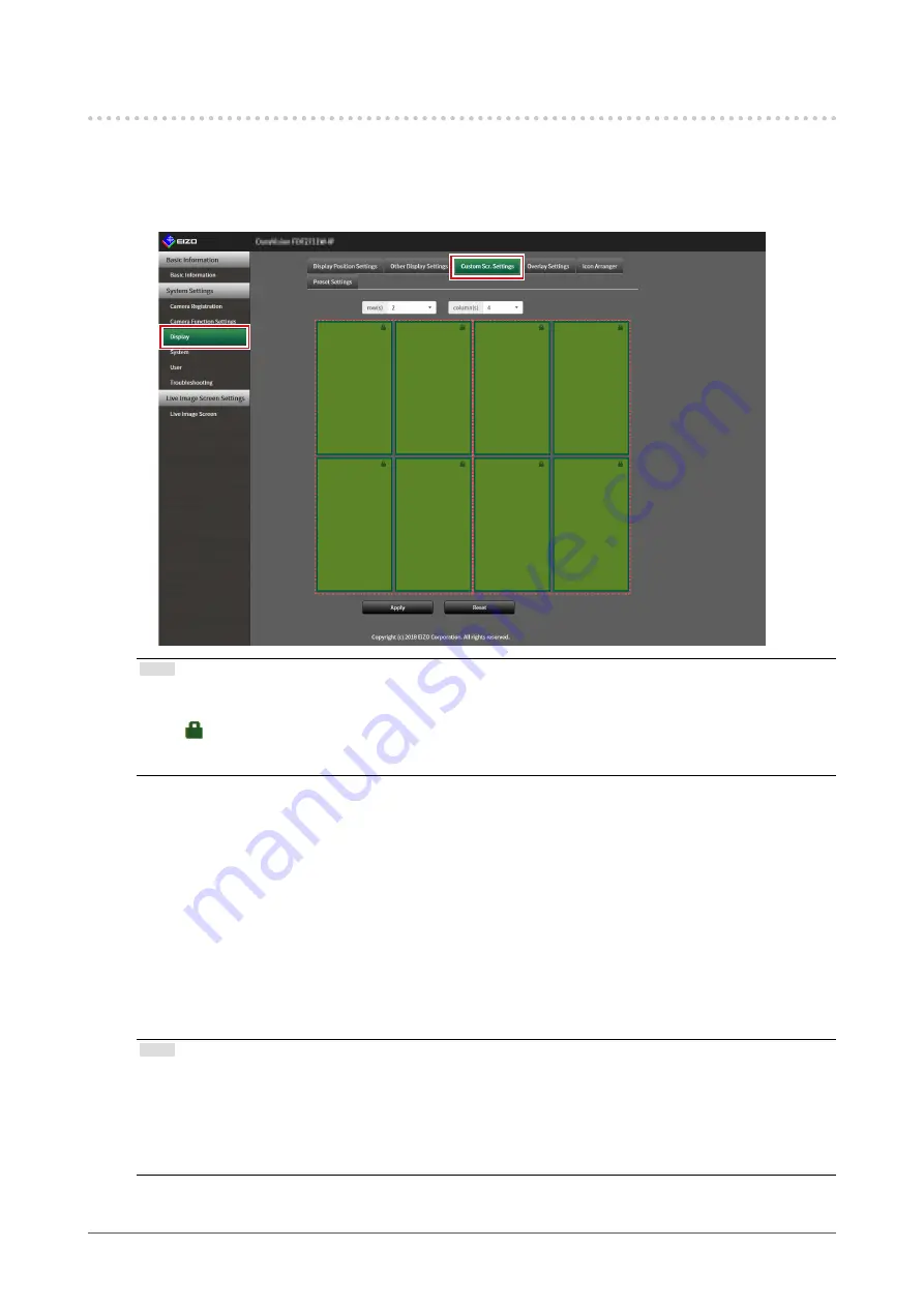
Custom Scr. Settings
” of “Display
”.
The “Custom Scr. Settings” screen is displayed.
Note
• When set to “Extended” in “Multi-Monitor”, the range displayed on each monitor is shown as a red, dotted
line.
• Click
in the display position frame to fix the display position of any camera image.
The display position for the specified camera image is maintained even if the pages are switched.
This function can only be used with “Custom Scr. Settings”.
2.
Select the number of “row(s)” and “column(s)
” from the list box.
The screen will change to a layout with the selected number of columns and rows.
3.
Drag a camera image display position and drop it on the display position you
want to couple with.
The selected display position is coupled.
4.
Select “
Apply”.
The display position coupling is updated. When “Reset” is selected, the information of the setting
being changed is discarded and the setting is reset to the current display setting of the product.
Note
• To release the coupling, click the display position just coupled. This can also be performed by changing the
number of columns and rows from the list box.
• If “Aspect Ratio Mode” is set to “Aspect”, “Full” or “Aspect” is displayed for the camera display position, and
the setting changes every time either one of them is selected.
• For information on setting “Aspect Ratio Mode”, see
“5-1. Setting Display Positions of Camera Video Images”
.


