7
Original instructions
> English
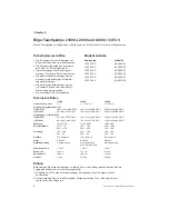
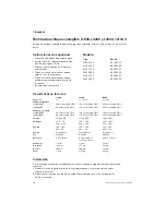
Maintenance
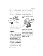
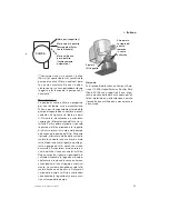
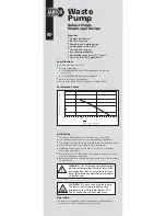
Regularly check the pump to be sure that the filter base and impeller are not clogged with
debris. To clean, push in the tabs and lift up the pump housing. Note! The discharge hose need
not be removed.
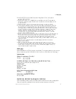
Accessories
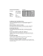
Panel 12 or 24 V
Part No: 12 V – 34-1224
24 V – 34-1225
Electrical installation with the Johnson Pump panel
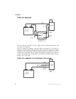
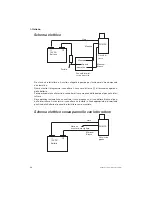
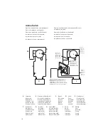
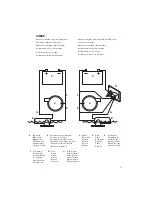
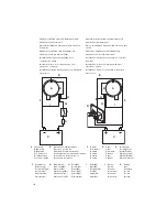
Always install according to the wiring diagram on page 16-18.
UltimaSwitch™
Part No: 34-36303
BilgeAlert™
Part No: 34-72303
Electronic Float Switch
Part No: 34-1900B-12V
34-1900B-24V
Automatic Float Switch
Part No: 34-888
Waste handling & material recycling
At the products end of life, please dispose of the product according to applicable law. Where
applicable, please disassemble the product and recycle the parts material.
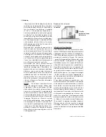
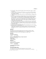
3. Position the strainer so that the pump nozzle is in the proper position to connect to the
discharge
hose.
4. Mount the strainer. If attaching the strainer to wood, fasten with stainless steel screws. If
attaching the strainer to metal or fiberglass, first mount a wooden block and then fasten
the strainer to the wooden block.
5. Mount the pump on the strainer so that both locktabs ”snaps” into place.
6. Select a point where the bilge water is to be pumped overboard as high as possible
above the water line and at the shortest distance from the pump. Install a 1½"[L2200/
L4000] or 1¹⁄
8
" [L1600/L2200] or 2"[L4000] thru-hull fitting. Note: The L4000 pump comes
equipped with an integrated check valve to minimize back flow of water, however, over
time water will seep back into the hull when the pump is not running. The use of flapper
check valve will reduce maximum flow performance.
7. Fasten a 1½"[L2200/L4000] or 1¹⁄
8
" [L1600/L2200] or 2"[L4000] fuel resistant hose
from the pump outlet to the thru-hull fitting. Avoid sharp bends or loops. Support the hose
if necessary. Note: In order to prevent air locks it is important that the hose not be allowed
to dip below the pump outlet. The hose should be constantly rising.
8. Connect the brown wire to the positive (+) terminal of the battery, and the black wire to
the negative (-) termal of the battery. See wiring diagram, page 16-17.
9. Important: All electrical wiring must be clamped with the connections well above the
bilge water level. Do not remove the insulation more than necessary. All wiring connec-
tions should be sealed with a marine sealant to avoid oxidation
Summary of Contents for 268 Center Console
Page 1: ...268CC 268 Center Console OWNER ASSISTANCE MANUAL Revised 2014...
Page 32: ...31 Appendix 268CC...
Page 33: ...34...
Page 34: ...35 Hydraulic Steering System...
Page 35: ...36...
Page 36: ...37...
Page 37: ...38...
Page 38: ...39...
Page 39: ...40...
Page 40: ...41...
Page 112: ......
Page 129: ......
Page 146: ...8 Rotation of Ports 1 2 3 4 5 6 7 1 Rotation of Pump Head 2 3 4 5...
Page 186: ...38 A B 50 mm C 20 mm...

