


11
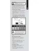
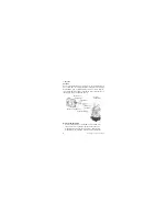
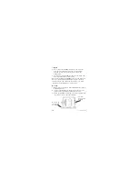
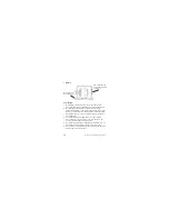
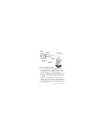
Wiring:
1. Connect the remote manual switch and inline fuse between
the battery and the UltimaSwitch.
2. The wiring connections should be made with water resistant
permanent terminals. Liquid electrical tape should be used to
coat the terminals. The mount connections should be above
the highest water level.
3. The Brown with White Tracer (+) UltimaSwitch wire should
be attached to the fused wire from the positive terminal.
4. The Brown relay UltimaSwitch wire to the Brown (+) pump
wire.
5. The Black (-) pump wire to the negative battery terminal.
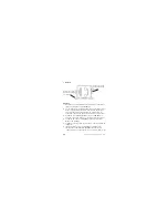
6. 2 Way Dash Panel Switch Auto/On Operation. Connect
brown switch wire lead and brown positive (+) pump wire
lead to positive (+ ON position) of dash panel switch.
Connect brown with White Tracer switch wire lead to positive
(+) battery terminal (in line fuse required).
7. 2 Way Dash Panel Switch OFF/ON Operation. Connect
brown switch wire lead to brown positive (+) pump wire lead.
Connect brown with white tracer switch wire lead to positive
(+ On Position) of panel switch (Inline fuse required)
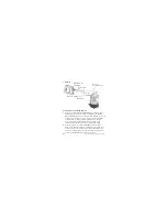
8. 3 Way Dash Panel Switch ON/OFF/Auto Operation. Connect
brown switch wire lead and brown positive (+) pump wire
lead to positive (+ ON Position) of dash panel switch.
Connect Brown with white tracer switch wire lead to positive
(+ Auto Position) of panel switch (Inline fuse required). Black
negative (-) wire lead from pump always to ground.
Original instructions
> English
Summary of Contents for 268 Center Console
Page 1: ...268CC 268 Center Console OWNER ASSISTANCE MANUAL Revised 2014...
Page 32: ...31 Appendix 268CC...
Page 33: ...34...
Page 34: ...35 Hydraulic Steering System...
Page 35: ...36...
Page 36: ...37...
Page 37: ...38...
Page 38: ...39...
Page 39: ...40...
Page 40: ...41...
Page 112: ......
Page 129: ......
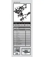
Page 146: ...8 Rotation of Ports 1 2 3 4 5 6 7 1 Rotation of Pump Head 2 3 4 5...
Page 186: ...38 A B 50 mm C 20 mm...


