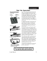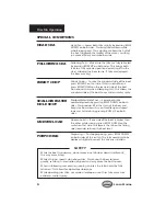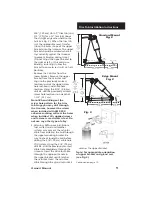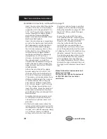
Method 1. (Preferred)
Step One.
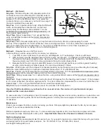
With the compass in its intended position, but
not finally secured, (see Mounting the Compass) select a
course on your chart using two fixed aids that are within ten
degrees (10°) of the North/South line. Try to select this
course so that you can maneuver your boat “down range” of
the marks selected (See example).
Step Two.
From a position down range of the North/South
marks, and keeping the marks lined up, run the boat
visually along the Northerly course selected. Turn the
port/starboard compensator (slot is facing starboard) until
the compass reads correctly.
Step Three.
Simply repeat steps 1 & 2, except this time,
using an East/West course and the fore/aft compensator
(slot is facing aft).
Step Four.
Check compass alignment by running the boat in a Southerly direction, again keeping the mark
lined up. If the compass is not correct at this time, there is an alignment error. To correct, rotate the compass itself to
remove one half of this error. Repeat steps 1, 2 & 4 until your North/South line is correct then repeat step 3.
Step Five.
Install fastener (s), taking care not to disturb alignment.
Method 2.
(Requires the use of GPS or Loran)
In this method you will be using a GPS or Loran as your reference.
1. Your GPS or Loran must be set to provide you with Magnetic, not True headings. Check your Manual.
2. GPS and Loran provide headings based on COG (course over ground). Compasses provide heading based on
the direction the boat is actually pointed. Because of Tides, Currents and Winds, the boat may not always point in
the same direction as COG. Pick a time and location that will minimize these effects.
3. Because the GPS and Loran calculate COG based on current and past positions you will see greater heading
accuracy while traveling at higher speeds. We recommend at least 10 knots.
Step One.
While at sea, with the compass in its intended position, but not finally secured, (see Mounting the Compass),
obtain the Loran/GPS bearing to a fixed aid or landmark that is within 10
o
of a North/South line.
Step Two.
Position your boat along that line and steer directly at that mark. Turn the port/starboard compensator (slot is
facing starboard) until the compass heading matches the Loran/GPS bearing.
Step Three.
Simply repeat steps 1 & 2, except this time, using an East/West course and the fore/aft compensator (slot is
facing aft).
Step Four.
Check compass alignment by running the boat 180 degrees from the heading used in step 2. If the compass
is not correct at this time, there is an alignment error. To correct, rotate the compass itself to remove one half of this error.
Repeat steps 1, 2 & 4 until your North/South line is correct then repeat step 3.
Step Five
. Upon completing the procedure, secure the compass in its final position.
If you feel that the deviation on your boat is of an unusual nature, the services of a professional compass
adjuster will be a wise investment.
To assure accuracy on all headings, check for deviation every thirty degrees and record any deviation on a deviation card.
We recommend checking at the start of each boating season, and any time new equipment is added near the compass,
for deviation.
Maintenance
Protect your compass from the sun when not using your boat. Strong sunlight may decrease the life of your compass.
Custom fit covers are available from Ritchie.
Ritchie compasses require very little care. To remove salt spray deposits or dirt, rinse the entire compass with clean,
fresh water and wipe carefully with a damp cloth.
Important Note: Never Use Chemical or Abrasive Cleaners.
Night Lighting Systems
Ritchie’s night-lights are designed to last for years of use. If you need to replace one, contact the factory with your model
and serial number for a part number and price. Tel. 781-826-5131 Fax. 781-826-7336 E-mail
[email protected]
LIGHTHOUSE
DOWN RANGE
TOWER
EXAMPLE
LIGHTHOUSE
Summary of Contents for 268 Center Console
Page 1: ...268CC 268 Center Console OWNER ASSISTANCE MANUAL Revised 2014...
Page 32: ...31 Appendix 268CC...
Page 33: ...34...
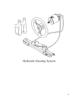
Page 34: ...35 Hydraulic Steering System...
Page 35: ...36...
Page 36: ...37...
Page 37: ...38...
Page 38: ...39...
Page 39: ...40...
Page 40: ...41...
Page 112: ......
Page 129: ......
Page 146: ...8 Rotation of Ports 1 2 3 4 5 6 7 1 Rotation of Pump Head 2 3 4 5...
Page 186: ...38 A B 50 mm C 20 mm...

