Maintenance
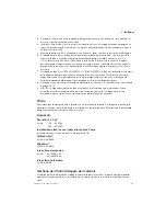
Check all electrical connections periodically, particularly in salt
water areas. Corrosion can cause loss of performance or non-
operation in extreme cases. The motor should be protected
with a corrosion inhibiting spray and any rust should be
removed and the motor repainted.
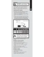
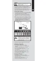
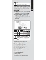
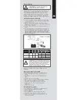
Wiring Instructions
G
Make all electrical connections in dry locations; connections
in humid environments should be sealed to prevent
corrosion.
G
Protect the circuit with a rated fuse or circuit breaker in the
red positive (+) lead as close as possible to the power
source.
G
Connect the black motor wire to the negative (-) battery
terminal.
G
Inadequate voltage at the motor terminals when the pump
is running (not less than 10% below rated voltage at full
load) due to partially discharged batteries or insufficient
cable size may result in blowing fuses, failure to start or
poor pump performance.
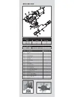
Ensure sterilization of wet end before disassembly.
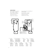
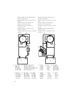
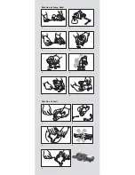
Rotation of Pump Head
(See diagrams on inside back cover)
1. Push down on clip and remove end cover
2. Internal bolt heads now exposed
3. Undo all four mounting bolts
4. Remove bolts and grasp motor unit firmly
5. Rotate pump head to desired position
6. Example of pumps rotational capabilities
7. Replace all 4 internal bolts and secure tightly
8. Replace end cover
Rotation of Ports
(See diagrams on inside back cover)
1. Undo clamp using allen key
2. Remove clamp
3. Rotate port unit to desired location
4. Example of pumps rotational capabilities
5. Replace clamp and tighten until firmly secure
WARNING: Always disconnect pump from
power supply.
WARNING: If the fuse fails repeatedly do
not fit a heavier fuse or bridge the fuse
terminals with silver paper or metal wire.
Failure to observe this instruction may
result in a fire hazard due to overheating
of cables.
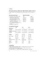
Max
Max
Wiring size*
Model No
Voltage Current
Fuse
Max.
Size
AWG
mm
2
Length
50890-1000
12V
8A
10A
14
2.5
4.5m (15ft)
14
2.5
9.0m (30ft)
50890-1100
24V
2.5A
5A
14
2.5
4.5m (15ft)
14
2.5
9.0m (30ft)
*for longer installations, fit thicker cables
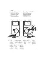
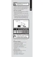
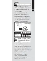
Overload
Protected
Distribution
Panel
ORANGE
WIRE
BLACK
WIRE
FUSE
OUTLET PORT
INLET
PORT
Wiring Diagram
BATTERY
Summary of Contents for 268 Center Console
Page 1: ...268CC 268 Center Console OWNER ASSISTANCE MANUAL Revised 2014...
Page 32: ...31 Appendix 268CC...
Page 33: ...34...
Page 34: ...35 Hydraulic Steering System...
Page 35: ...36...
Page 36: ...37...
Page 37: ...38...
Page 38: ...39...
Page 39: ...40...
Page 40: ...41...
Page 112: ......
Page 129: ......
Page 146: ...8 Rotation of Ports 1 2 3 4 5 6 7 1 Rotation of Pump Head 2 3 4 5...
Page 186: ...38 A B 50 mm C 20 mm...

