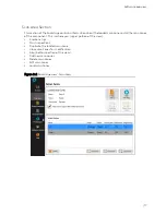
Lyft System Overview
| 3
1.
Power button
Short press (approximately 0.5 to 4 seconds):
Use to turn the instrument on and off. The
power indicator at the center of the button
behaves as follows:
•
Green: Lyft is on
•
Blinking yellow/orange: Lyft is on standby
•
Unlit: Lyft is off
Long press (approximately greater than 4
seconds):
If the instrument is on, a long press will initiate
a forced shutdown.
If the instrument is off, a long press will
activate RDAU mode, which allows the user to
operate the instrument remotely from a
laptop. Press and hold the power button until
the alarm indicator light flashes, then release
the power button. The power button light will
continue to flash while in RDAU mode.
2.
Battery indicator
Displays the state of Lyft’s batteries when the
instrument is on. Depending on the power
mode (DC or battery), the indicator behaves
differently:
DC power
•
Green: batteries fully charged
•
Blinking green: batteries charging
•
Red: battery or charger error
•
Unlit: no batteries in Lyft
Battery power
•
Unlit: remaining charge over 40 %
•
Orange: remaining charge 20–40 %
•
Blink yellow: remain. charge less than 20 %
•
Red: battery error
3.
Wi-Fi indicator
Displays the Wi-Fi status. When the indicator
is lit, the Wi-Fi is enabled. When it is off, the
Wi-Fi is disabled.
4.
Alarm indicator
Used to display user- programmed errors. The
indicator remains unlit until it detects a
predefined error condition, at which time it
lights red.
5.
Wall thickness calibration button
Use to perform a wall thickness calibration at
the nominal thickness. A short press calibrates
on a new point, while a long press calibrates
on the data at the cursor’s location.
6.
Index button
Use to increment the index line during data
acquisition.
7.
Get point button
Only use during data acquisition in grid-
mapping mode. It allows performing a
measurement at the cursor coordinates.
8.
Start / Stop acquisition button
Use to start or stop data acquisition.
9.
Heavy-duty bumpers
The four corner bumpers provide shock
absorption and support Lyft at an angle when
it is set on a flat surface. The bumpers are also
hooked for harnessing. For details about
harnessing, see page 84.
10.
Multi-touch display
10.4
″
, non-reflective, high-resolution display.
11.
Handle
Use this handle when carrying Lyft.
12.
Keypad arrow mode selection/ Disable
touchscreen button
Press to select the operation mode of the
keypad arrows (see 13). Long press this button
to disable or enable the touchscreen
(depending on its state). Follow the
instructions on the screen to complete the
operation.
13.
Keypad arrows
Use these arrows to navigate the Lyft software
interface according to the selected mode.
14.
Enter button
Enter key. Closes text boxes.
15.
Change active view button
Press to activate a different view than the one
currently active.
16.
Data display button
When PEC array probes are connected to the
instrument: used to activate the Probe Guides
in the C-Scan. Unused with single-element
probes
.
17.
Maximize/Minimize view button
Use this button to maximize or minimize the
active view.
18.
Change layout button
Use this button to change the Lyft software
layout to another predefined one.
Summary of Contents for LYFT
Page 1: ...i EDDYFI LYFT Corrosion Assessment Redefined User s Manual...
Page 11: ...General Precautions and conventions xi General Precautions and conventions...
Page 17: ...Lyft System Overview 1 Chapter 1 Lyft System Overview...
Page 30: ...14 eddyfi com...
Page 31: ...Software overview 15 Chapter 2 Software overview...
Page 47: ...Workflow overview 31 Chapter 3 Workflow overview...
Page 48: ...32 eddyfi com TYPICAL Inspection Workflow Figure 3 1 Typical inspection workflow...
Page 68: ...52 eddyfi com...
Page 69: ...Lyft PRO software 53 Chapter 4 Lyft PRO software...
Page 73: ...Lyft PRO software 57...
Page 74: ...58 eddyfi com Chapter 5 Preferences...
Page 78: ...62 eddyfi com...
Page 79: ...Keypad and Keyboard Functions 63 Chapter 6 Keypad and Keyboard Functions...
Page 81: ...Maintenance and Troubleshooting 65 Chapter 7 Maintenance and Troubleshooting...
Page 90: ...74 eddyfi com...
Page 91: ...Specifications 75 Chapter 8 Specifications...
Page 94: ...78 eddyfi com...
Page 95: ...Connector reference 79 Appendix A Connector reference...
Page 99: ...Using the Optional Harness 83 Appendix B Using the Optional Harness...
Page 109: ...Setting Up the Extension Pole 93 Appendix C Setting Up the Extension Pole...
Page 113: ...Using the array probe straps 97 Appendix D Using the array probe straps...
Page 119: ...License management 103 Appendix E License management...
Page 121: ...License management 105 Today Two weeks later YourComputerID...


