


Power Line Coupling Details
The coupling circuits shown in figures 4.4 and 4.5 require the addition of a small
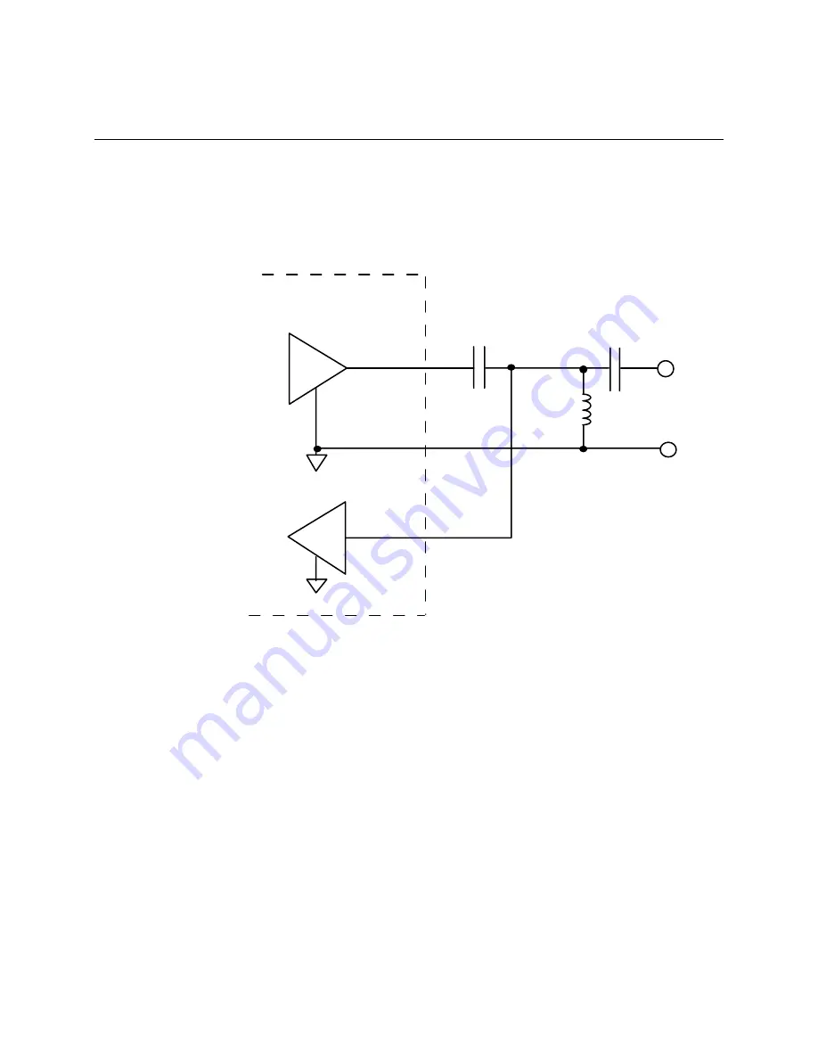
number of components to make them practical. Figure 4.6 shows the addition of an AC
coupling capacitor (C2) to prevent the inductor from shorting the transmit amplifier's
DC bias voltage.
Transmit
Amp
Receive Front End
PLT-22
C1
C2
L1
Figure 4.6
Simplified Coupling Circuit with Blocking Capacitor
Given the attenuation model presented earlier in figure 4.2, one critical design
constraint is that the series combination of C1 and C2 must have a low impedance at
the PLT-22 transceiver's communication frequencies. The impedance of these
capacitors, along with the PLT-22 transceiver's transmit output impedance,
corresponds to “Zo Transmitter” in figure 4.2. Since the equivalent load impedance of
the power line may in some cases be as low as 1-2 Ohms, and since the output
impedance of the PLT-22 transceiver is less than 1 Ohm, the impedance of these
capacitors should be on the order of 1 Ohm so that they do not add significantly to “Zo
Transmitter”. While the values of C1 and C2 could be set high enough to meet this
goal, doing so would significantly increase the cost of the high-voltage capacitor C1.
Since C2 is connected only to low voltage, and thus is lower cost for a given value, its
value can be set higher relative to the value of the high-voltage capacitor C1. A simple,
cost-effective solution is obtained when an inexpensive inductor, L2, is added as shown
in figure 4.7 below. This inductor forms a series-resonant circuit with C1 and C2, and
its value can therefore be chosen to optimize coupling at the PLT-22 transceiver's
communication frequencies while minimizing the cost of C1 and C2.
4-8
Coupling Circuits
Summary of Contents for LONWORKS PLT-22
Page 6: ...iv Echelon...
Page 14: ...1 8 Introduction...
Page 67: ...LONWORKS PLT 22 Transceiver s User Guide 5 7 Figure 5 3 Capacitor Input Power Supply Schematic...
Page 92: ...6 10 Design and Test for Electromagnetic Compatibility...
Page 110: ...7 18 Communication Performance Verification...
Page 114: ...8 4 References...
Page 118: ...A 4 Appendix A...


