


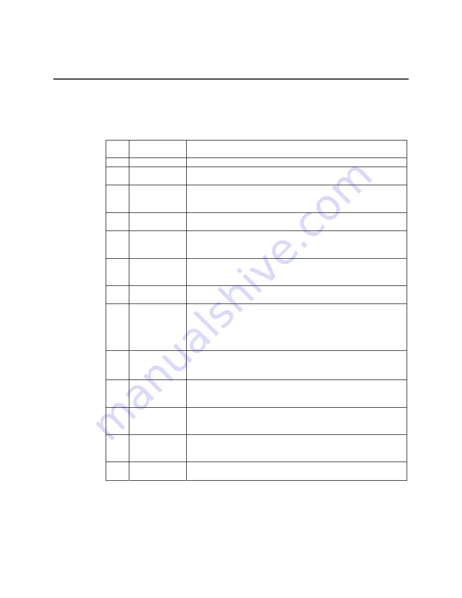
PLT-22 Transceiver-based Node Checklist
PLT-22 Transceiver and Neuron Chip Connections
Item Check
When
Completed
Description
1
Transceiver pins connected as shown in table 2.1.
2
Environmental and electrical specifications shown in table
2.2 and figure 2.2 .
3
10 MHz parallel resonant crystal with a load capacitance
rating of 13 pF to 20 pF is connected to the PLT-22
transceiver.
4
Clock frequency measured to be 10.0000MHz ±200ppm
(including allowance for temperature variation).
5
The recommended number and placement of 0.1µF bypass
capacitors are near the Neuron Chip. See the
Neuron Chip
Data Book
from Toshiba or Motorola.
6
The Neuron Chip input clock is
≥
1.25MHz for single carrier
frequency mode and
≥
2.5MHz for dual carrier frequency
mode.
7
The traces connecting the crystal to the transceiver are not
greater than 20mm (0.8") in length.
8
External 120µF [minimum] 16VDC, aluminum electrolytic,
low-ESR [<0.3
Ω
@ 100kHz] V
A
capacitor is used. The
capacitor must be exactly 16VDC (no higher or lower) to
meet surge suppression levels. Verify suitable capacitor
lifetime rating.
9
V
A
bypass capacitor is placed as close as possible to the
transceiver with low-impedance ground and supply traces
between the PLT-22 transceiver and the capacitor.
10
The three transceiver ground pins are connected with low-
impedance traces, or a ground plane, between the
transceiver and the Neuron Chip.
11
If used, the transceiver BIU and PKD are connected to low-
current (
≤
8mA) LEDs via series current-limiting resistor
connected to ground.
12
The BIU and PKD signals are connected to ESD protection
diodes if a plastic or metal enclosure without a good ground
connection is used.
13
The Neuron Chip CP3 pin is not connected and is left
floating.
B-2
Appendix B
Summary of Contents for LONWORKS PLT-22
Page 6: ...iv Echelon...
Page 14: ...1 8 Introduction...
Page 67: ...LONWORKS PLT 22 Transceiver s User Guide 5 7 Figure 5 3 Capacitor Input Power Supply Schematic...
Page 92: ...6 10 Design and Test for Electromagnetic Compatibility...
Page 110: ...7 18 Communication Performance Verification...
Page 114: ...8 4 References...
Page 118: ...A 4 Appendix A...


