Installation
Eaton 9135 5000/6000 VA UPS User’s Guide 164201726—Rev 4
www.eaton.com/powerquality
26
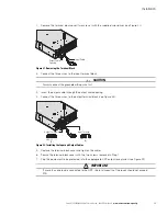
RPO Installation
Installation of the RPO function must be carried out in compliance with applicable regulations. The cable is not
included.
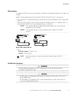
In order to fully de-energize devices and the Eaton 9135 UPS with the RPO port, it is necessary to:
l
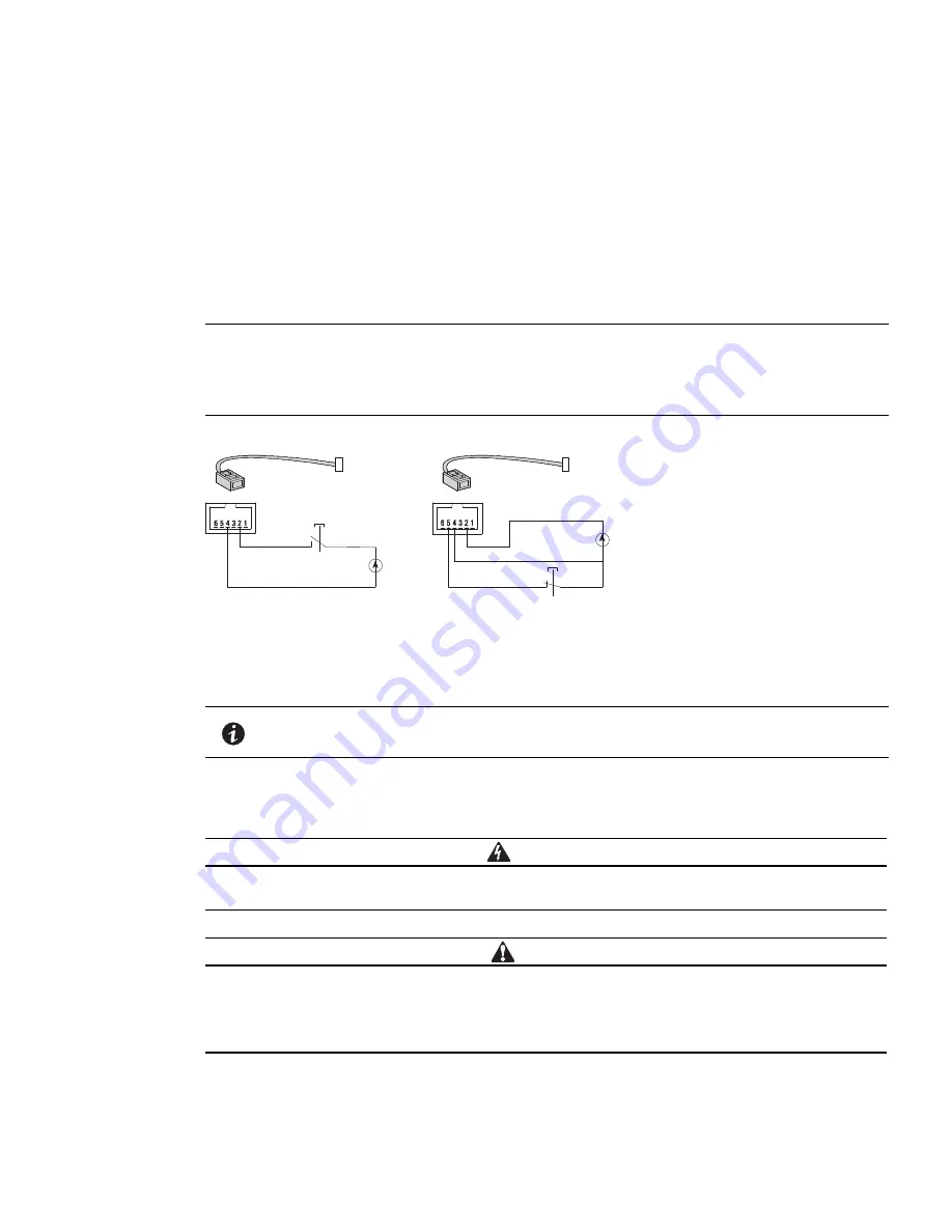
Use a two-position switch (normally-open or normally-closed contact and held more than one second). See
Figure 18.
l
Connect this RPO switch to a device that trips all breaker(s) located upstream
(NOTE 1)
and downstream
(NOTE 2)
from the Eaton 9135 UPS. This can be achieved by means of a shunt trip.
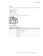
Figure 19. RPO Communication Port
l
Signal:
- -
Activation voltage:
5 Vdc to 27 Vdc
- -
Current:
10 mA maximum
UPS Electrical Connections
WARNING
Only qualified service personnel (such as a licensed electrician) shall perform the electrical
installation. Risk of electrical shock.
CAUTION
l
For UPS models with hardwired outputs, overcurrent protection for the output AC circuit(s) is to
be provided by others.
l
For UPS models with hardwired outputs, suitably rated disconnect switches for the output AC
circuit(s) are to be provided by others.
NOTE 1
If not, the output devices could be powered again through static switch when the
two-position switch is released.
NOTE 2
If not, the output devices will remain powered several seconds after the RPO
activation.
NOTE
The internal batteries will remain connected to the power module after RPO
activation.
RPO Contact Normally-Open
RPO Contact Normally-Closed
5
V
dc to 27
V
dc
5
V
dc to 27
V
dc
)
c
6
p
6
(
2
1
-
J
R
)
c
6
p
6
(
2
1
-
J
R


