72
Technical Data
PR202-50-502-22
Effective June 2017
CF2000 System
EATON
www.eaton.com
Intrinsically Safe Zone Monitor Unit Wiring
CZMU352-IS
To install the device
1.
Separate the two halves of the unit .
2.
Drill out (or knock out) the required cable entries in the surface
mounting backbox .
3.
Fit the back-box in position and pass the wires into it .
4.
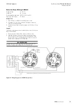
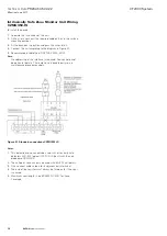
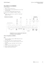
Connect the unit according to the diagram in Figure 51 .
5.
Recommended Cable Type: FIRETUF, FP200, MICC
ote:
N
No addressing of the interface is required . See control panel
operation for details . There are no serviceable parts so no
maintenance procedures apply .
Figure 51. Standard connections CZMU352-IS
otes:
N
1.
This detection zone can only be used with intrinsically safe
detectors SLR-E-IS (optical)/ DCD-1E-IS (heat) with the non-
diode base YBN-R/4IS .
2.
The call point zone can only be used with BG3 I/S call points .
3.
Only connect cable screen to its adjacent earth terminal .
4.
The end of line resistor must always be fitted, each if the spur
is unused .
5.
Maximum spur length - See BS5839 Pt1:2001 for Zone
Coverage .

