69
Technical Data
PR202-50-502-22
Effective June 2017
CF2000 System
EATON
www.eaton.com
3 Way Input/Output unit CIO351, CIO351S, CIO351SST
Install the device as follows .
1.
Separate the two halves of the unit .
2.
Drill out (or knock out) the required cable entries in the surface mounting back-box .
3.
Fit the back-box in position and pass the wires into it .
4.
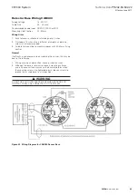
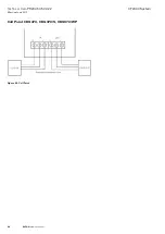
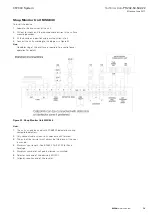
Connect the unit according to the diagram below .
Note:
No addressing of the interface is required . See control panel operation for details .
Figure 48 shows the standard connections .
Figure 48. Wiring for 3 way Input/Output unit CIO351
Notes
1.
Only connect cable screen to its adjacent earth terminal .
2.
The end of line resistor must always be fitted, even if the inputs are unused .
3.
Monitored inputs can detect open or short circuit faults .
4.
Output relays are volt-free contacts and are not monitored .

