


4- & 8-Channel Digital Video Recorder
57
NOTE: Any image adjustments you make will be applied to both the live video on the
monitors and the recorded video.
NOTE: The
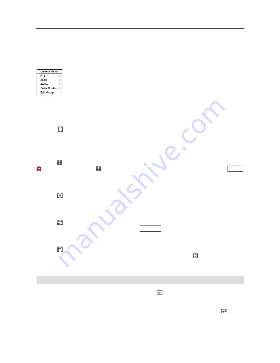
Camera Menu
also can be displayed by clicking the right mouse button on the
screen while in the live monitoring mode.
Alarm
Selecting
(Alarm) in the Live Monitoring menu resets the DVR’s outputs including the internal
buzzer during an alarm.
It is the same as pressing any button on the front panel when the alarm
is activated.
Panic
Selecting (Panic) in the Live Monitoring menu starts panic recording of all cameras, and displays
on the screen. Selecting
again stops panic recording. It is the same as pressing the
PANIC
button on the front panel.
Setup
Selecting
(Setup) in the Live Monitoring menu enters the Main Setup screen. Refer to
Chapter 3
Configuration
for detailed descriptions of system setup.
Search Mode
Selecting
(Search Mode) in the Live Monitoring menu exits the live monitoring mode and enters
the search mode. It is the same as pressing the
SEARCH
button on the front panel.
Login/Logout
Selecting
(Login) in the Live Monitoring menu accesses the Login screen, and you will be asked
to select a User and enter the password to log into the system. Selecting
(Logout) in the Live
Monitoring menu displays the Logout screen asking you to confirm whether or not you want to
log out the current user
.
Active Cameo Mode
You can enter the Active Cameo mode by pressing the
(Enter)
button on the remote control
or selecting
Edit Group
in the Camera Menu displayed when clicking the right mouse button in
any multi-view format. (8-ch Model Only) The yellow outline surrounding the video indicates
the active cameo, and pressing the arrow buttons moves the active cameo. Pressing the
(Enter)
button or selecting
Exit Group Edit
in the Camera Menu exits the Active Cameo mode. The active
cameo mode will remains in effect for 15 seconds if there is no further operation.
y
Edit Group:
Selecting
Edit Group
supports the active cameo function. (8-ch
Model Only) Select
Edit Group
and choose a camera that you want to change
display position (e.g., Camera A). Then, click the right mouse button to display
the menu. If you choose another camera in the menu (e.g., Camera B), the screen
displays Camera B instead of Camera A. Clicking the right mouse button and
selecting
Exit Group Edit
in the menu exits the Active Cameo mode. Refer to
the following
Active Cameo Mode
section for details.
Summary of Contents for E-DVR-104
Page 1: ......
Page 2: ......
Page 62: ...User s Manual 54 ...


