D
YNACORD
14
18 – SPEAKER D
ELAY
BUTTON
Pressing the Delay button places the current preset in Edit mode and jumps to the SPEAKER Delay screen. Subsequent
button presses step through the available output channels (depending on configuration).
19 – SPEAKER L
EVEL
BUTTON
Pressing the Level button places the current preset in Edit mode and jumps to the SPEAKER Level screen. Subsequent
button presses step through the available output channels (depending on configuration).
Press and hold the SPEAKER Level button for 4 seconds to open the Limiter screen. Subsequent button presses step
through the available output channels (depending on configuration).
20 – O
UTPUT
LEVEL
METERS
Each output channel has an eight-segment output level VU meter. Meter response characteristics can be selected in the
Setup menu:
The yellow segment indicates that there is no headroom left to the selected VU reference i.E. D/A Converter Clip or Lim-
iter Threshold. The red segments indicates clipping within the output signal path and should be avoided by adjusting
the Output Level of the output channel. It is important to understand how the meters work and what they are displaying.
The Output Meters are displayed as “dB to Limiter Threshold” or „dB to D/A clip”. In other words, these meters will
display the headroom between the output level and the limiter threshold or clip threshold of the D/A converter. When
viewed in conjunction with the Gain Reduction meters, this provides a complete display of level and headroom before
and after limiting has been engaged to allow system levels to be optimized. This also means that the output metering
will be displayed differently depending on the limiter threshold setting.
21 – O
UTPUT
GAIN
REDUCTION
METERS
Each output channel has a four-segment gain reduction meter that shows the effect of the output channel Limiter on
output signal; from -3dB to -12dB.
22 – O
UTPUT
CHANNEL
M
UTE
BUTTONS
Each output channel has a lighted Mute button. Pressing the Mute button turns off the output of that channel. The but-
ton lights red as an alert. Press the Mute button again to restore the output channel’s signal. Output channels may also
be muted from IRIS-Net Application, if the unit is connected to a PC. Muting a channel in any window of the application
will light the channel Mute button on the front panel of the unit as well.
23 – O
UTPUT
CHANNEL
FUNCTION
INDICATORS
Each output channel has a four-segment function display for informational purposes only. For any given configuration
possible with the DSP 600, an output channel may be identified as a sub, low, low/mid, mid, mid/hi, hi or full range
output. One or two adjacent LED are displayed to indicate all possible output bandpasses. (Full range is indicated by
no lit LED’s.)
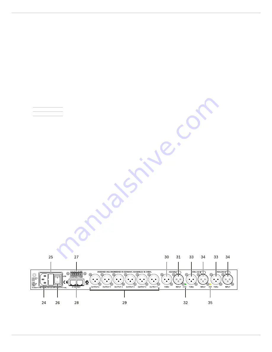
3.2 Rear Panel
• Normal Fast,
• Peak-Hold,
• Slow Decay.
Summary of Contents for DSP 600
Page 1: ...DSP 600 FIR TUNE SOUND SYSTEM PROCESSOR Owner s Manual Bedienungsanleitung Mode d emploi...
Page 5: ...DSP 600 5...
Page 46: ...DYNACORD 46...
Page 48: ...DYNACORD 48 1 bersicht...
Page 89: ...DSP 600 89...
Page 92: ...DYNACORD 92...
Page 136: ...DYNACORD 136 8 3 Signal flow chart...
Page 138: ...DYNACORD 138 9 3 12 dB PEQ Cuts Q Changes 9 4 12dB Oct Shelves at 200 Hz and 2 kHz...
Page 139: ...DSP 600 139 9 5 Bessel Filters 9 6 Butterworth Filters...
Page 140: ...DYNACORD 140 9 7 Hi Lo Pass Filters 9 8 Linkwitz Riley Filters...
Page 142: ...DYNACORD 142...
Page 143: ...DSP 600 143...


