background image

Changing the sewing motor

98

Service Instructions 755 A/756 A - 00.0 - 02/2019

15 Changing the sewing motor

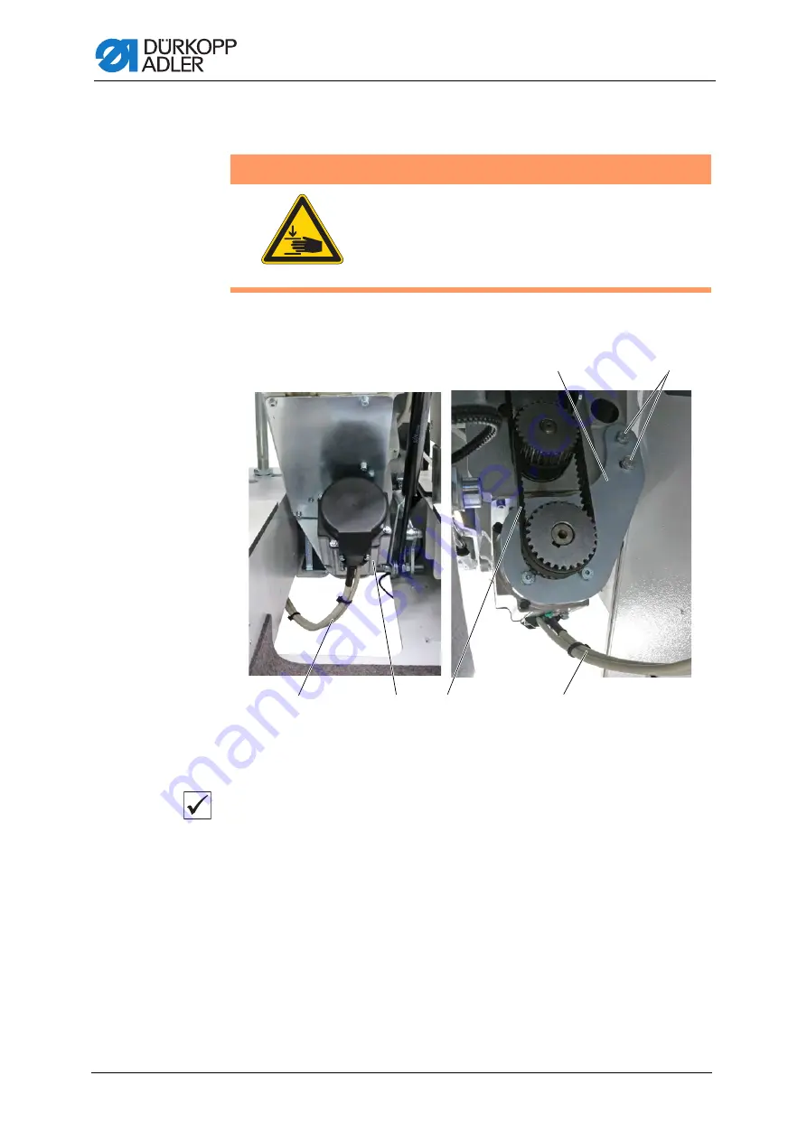
Fig. 103: Changing the sewing motor (1)

Proper setting
For non-switchable needle bar:

The sewing motor position must be 40°. The position is indicated at 
the handwheel.
When the position is 40°, the thread lever is positioned approx. 5 mm 
in front of the top dead center.

For switchable needle bar:

The sewing motor position must be 60°. The position is indicated at 
the handwheel.
When the position is 60°, the thread lever is positioned approx. 5 mm in 
front of the top dead center.

WARNING

Risk of injury from moving parts!

Crushing possible.

Switch off the machine before changing the sewing 
motor.

(1)

- Sewing motor cable

(2)

- Sewing motor

(3)

- Toothed belt

(4)

- Screws

(5)

- Sewing motor holder

Summary of Contents for 755 A

Page 1: ...755 A 756 A Service Instructions...

Page 2: ...er AG and protected by copyright Any reuse of these contents including extracts is prohibited without the prior written approval of D rkopp Adler AG Copyright D rkopp Adler AG 2019 IMPORTANT READ CARE...

Page 3: ...edle bar with the throat plate 28 6 1 2 Setting the needle bar height 32 6 1 3 Changing the needle holder 34 6 1 4 Disassembling the needle bar linkage 35 6 1 5 Assembling the needle bar linkage 37 6...

Page 4: ...ice 96 14 1 Adjusting the needle thread quantity 96 14 2 Setting the movement of the needle thread advancing device 97 15 Changing the sewing motor 98 16 Setting the folding station plate 101 17 Folde...

Page 5: ...1 3 Setting the corner knife inclination 151 21 1 4 Testing the initial position of the corner knives manually 153 21 2 Testing and adjusting the corner knives electrically 156 21 3 Aligning the corne...

Page 6: ...driver zipper 218 26 6 Setting the folder height when the zipper is cut 219 27 Additional equipment 221 27 1 Setting the outfeed roller 221 27 2 Tape feeder 223 27 2 1 Assembling the tape feeder and...

Page 7: ...30 3 Servicing the pneumatic system 443 30 3 1 Setting the operating pressure 443 30 3 2 Draining the water condensation 444 30 3 3 Cleaning the filter element 445 30 4 Parts list 446 31 Decommission...

Page 8: ...Table of Contents 6 Service Instructions 755 A 756 A 00 0 02 2019...

Page 9: ...intended These instructions are intended for Specialists This group has the appropriate technical training for performing maintenance or repairing malfunctions With regard to minimum qualification an...

Page 10: ...lay control panel Important Special attention must be paid to this point when performing a step Information Additional information e g on alternative operating options Order Specifies the work to be p...

Page 11: ...ndards and regulations D rkopp Adler cannot be held liable for any damage resulting from Breakage and damage during transport Failure to observe these instructions Improper use Unauthorized modificati...

Page 12: ...About these instructions 10 Service Instructions 755 A 756 A 00 0 02 2019...

Page 13: ...uld impair safety and damage the machine Only use original parts from the manufacturer Transport Use a lifting carriage or forklift to transport the machine Raise the machine max 20 mm and secure it t...

Page 14: ...used in warnings Warnings in the text are distinguished by color bars The color scheme is based on the severity of the danger Signal words indicate the severity of the danger Signal words Signal words...

Page 15: ...en fatal injury if ignored This is what a warning looks like for a hazard that could result in moderate or minor injury if the warning is ignored Puncture Crushing Environmental damage Symbol Type of...

Page 16: ...environmental damage if ignored This is what a warning looks like for a hazard that could result in property damage if ignored CAUTION Type and source of danger Consequences of non compliance Measure...

Page 17: ...at top dead center position 3 2 Locking the machine in place Fig 1 Locking the machine in place The arm shaft crank 2 is equipped with a large arresting groove 3 5 mm and a small arresting groove 5 3...

Page 18: ...n and checking the top dead center for the needle bar 3 3 Swiveling up the machine head The machine head can be swiveled up for maintenance work This requires that the transport carriage be in its rea...

Page 19: ...ve the fabric sliding plate 2 4 Swivel the locking lever 1 up Fig 3 Swiveling up the machine head 2 5 Lift and carefully swivel up the machine head The latch 3 locks into place as well The space below...

Page 20: ...ne head 1 To swivel down the machine head 1 Raise the machine head until the latch 1 disengages 2 Lower the machine head carefully NOTICE Property damage may occur Possible damage to the light barrier...

Page 21: ...755 A 756 A 00 0 02 2019 19 Fig 5 Swiveling down the machine head 2 3 Swivel the locking lever 2 down 4 Swivel down the folding station and lock it into place 5 Insert the fabric sliding plate 3 2 Lo...

Page 22: ...ot 1 1 Turn the handwheel until the 1st threaded pin is under the slot 1 2 Loosen the threaded pin through the slot 1 3 Turn the handwheel by 50 such that the 2nd threaded pin is under the slot 1 4 Lo...

Page 23: ...is at the same height as the tabletop along its entire length To align the machine head 1 Slide the transport clamps to the rear 2 Remove the sliding plate 3 Check the height of the base plate 1 using...

Page 24: ...rvice Instructions 755 A 756 A 00 0 02 2019 Fig 8 Aligning the machine head 2 4 Loosen the screws 4 5 Loosen the nuts 6 6 Use the screws 5 to set the machine head 7 Tighten the nuts 6 8 Tighten the sc...

Page 25: ...tructions 755 A 756 A 00 0 02 2019 23 Fig 9 Aligning the machine head 3 9 Swivel up the machine head 10 Loosen the screws 9 The mounting plate 7 is loose 11 Swivel down the machine head 7 Mounting pla...

Page 26: ...ad The throat plate 13 is positioned exactly in the slot of the fabric sliding plate 15 Tighten the nuts 12 16 Swivel up the machine head The centering device 10 centers the machine head in the mounti...

Page 27: ...t the transport carriage be in its rear position Fig 11 Disassembling the machine head 1 To remove the machine head 1 Swivel the folding station 1 out by 90 2 Remove the fabric sliding plate 2 3 Disco...

Page 28: ...sembling the machine head 2 4 Loosen the gas shock absorber connection 3 5 Loosen the screws 4 6 Use a suitable tool to carefully lift the machine head up and out 5 2 Assembling machine head Fig 13 As...

Page 29: ...machine head into the tabletop cutout 2 Tighten the machine head using the screws 2 3 Restore the gas shock absorber connection 1 Fig 14 Assembling machine head 2 4 Establish the electrical and pneuma...

Page 30: ...th the throat plate Proper setting The needles plunge into the center of the holes on the throat plate Setting the needle bar sideways Fig 15 Aligning the needle bar with the throat plate 1 WARNING Ri...

Page 31: ...screws 2 on the adjusting rings 5 Loosen the screws 1 on the crank pin Fig 16 Aligning the needle bar with the throat plate 2 6 Shift the needle bar linkage 4 The needles plunge into the center of th...

Page 32: ...2019 Setting the needle bar lengthwise Fig 17 Aligning the needle bar with the throat plate 3 To set the needle bar lengthwise 1 Remove the head cover 2 Removing the arm cover 3 Slightly loosen the sc...

Page 33: ...55 A 756 A 00 0 02 2019 31 Fig 18 Aligning the needle bar with the throat plate 4 5 Turn the needle bar linkage 3 such that the needles are at the center of the needle holes 5 6 Tighten the screw 1 3...

Page 34: ...height Fig 19 Setting the needle bar height 1 Proper setting Lock the machine in place at the loop stroke position p 15 The height of the needle bar is set correctly when the hook tip is positioned i...

Page 35: ...0 02 2019 33 Fig 20 Setting the needle bar height 2 To set the needle bar height 1 Loosen the screws 2 2 Remove the head cover 1 3 Loosen the screw 3 4 Set the needle bar height 4 5 Align the needle h...

Page 36: ...mble the middle knife 2 Remove the needles 3 Loosen the screw 3 4 Unscrew the needle holder 2 from the needle bar 1 5 Screw in a new needle holder all the way Next turn the needle holder back until th...

Page 37: ...machine 2 Disconnect the compressed air supply 3 Swing the folding station out 4 Remove head cover arm cover and motor cover 5 Remove the needles 6 Loosen the screw 3 7 Remove the middle knife 5 8 Loo...

Page 38: ...ver 8 completely out of the lever 8 The thread lever is loose Fig 24 Disassembling the needle bar linkage 3 15 Turn the handwheel until the next screws on the arm shaft crank are accessible 16 Loosen...

Page 39: ...Assembling the needle bar linkage 2 2 Slide the needle bar linkage onto the shaft 6 as far as it will go 3 Use a screw 12 to tighten the needle bar linkage through the arm shaft crank 4 The pin must...

Page 40: ...freely The thread lever 8 is automatically positioned correctly when the screws 9 on the face of the pin have been tightened 9 Slightly loosen the screws 9 and slowly complete 2 3 turns at the handwh...

Page 41: ...nkage can move freely 16 Turn the handwheel until the needle bar is at the top dead center 17 Insert the needles Fig 29 Assembling the needle bar linkage 5 18 Turn the handwheel until the needle bar i...

Page 42: ...plate Setting the needle bars sideways Fig 30 Aligning the needle bars with the throat plate 1 To set the needle bars sideways 1 Disconnect the compressed air supply 2 Remove the arm cover 3 Remove t...

Page 43: ...the center of the needle holes 6 on the throat plate 10 Tighten the adjusting rings and fasten the screws 2 11 Tighten the screw 3 12 Tighten the screws 1 Setting the needle bar lengthwise Fig 32 Alig...

Page 44: ...r tongues 1 so that they are parallel 5 Turn the needles to bottom dead center Fig 33 Aligning the needle bars with the throat plate 2 6 Turn the needle bar linkage 3 such that the needles are at the...

Page 45: ...needle bar is set correctly when the hook tip is positioned in the lower third of the groove on the needle Fig 35 Setting the needle bar height 2 To set the needle bar height 1 Turn the needles to to...

Page 46: ...r 1 Remove the needles 2 Loosen the screw 2 3 Unscrew the needle holder 3 from the needle bar 1 If necessary turn off the needle bar 4 Screw in the new needle holder until the screw 2 is centered in t...

Page 47: ...compressed air supply 3 Swing the folding station out 4 Remove head cover arm cover and motor cover 5 Remove the needles Fig 37 Disassembling the needle bar linkage 1 6 Disconnectthepneumatichoses 4 f...

Page 48: ...w 7 9 Remove the middle knife 9 10 Loosen the screws 6 11 Remove the middle knife guard 7 12 Loosen the screw 5 13 Remove the plate 10 from the felt Fig 39 Disassembling the needle bar linkage 3 5 Scr...

Page 49: ...ut of the lever 15 The thread lever is loose Fig 40 Disassembling the needle bar linkage 4 17 Turn the handwheel until the next screws on the arm shaft crank are accessible 18 Loosen the screws 16 19...

Page 50: ...kage Fig 41 Assembling the needle bar linkage 1 To assemble the needle bar linkage 1 Use a threading wire 1 to feed the oil wick 3 through the machine head Fig 42 Assembling the needle bar linkage 2 1...

Page 51: ...ack into the slot in the machine casting Fig 43 Assembling the needle bar linkage 3 8 Push the bolt 5 completely into lever 11 9 Push the bolt 5 further into lever 13 10 Tighten the screws 12 The thre...

Page 52: ...he gear tongues 15 by hand until they are parallel to one another 17 Slightly loosen the screw 14 The needle bar linkage can move freely 18 Turn the handwheel until the needle bar is at the top dead c...

Page 53: ...le bar linkage be set in the exact position relative to the needle bars Proper setting Fig 46 Assembling the needle bar linkage 6 The distance between needle bar linkage and clamping ring is 0 25 mm w...

Page 54: ...screwdriver through the slot below the handwheel and into the slot on the shaft 30 Turn the shaft and set the distance between needle bar linkage and clamping piece to 0 25 mm Use a feeler gage to ch...

Page 55: ...nect the pneumatic hoses 22 to the housing of the split needle bar 19 38 Open the menu Service Machine test Multi test I O to check the outputs of the split needle bar Output Y7 Needle left Output Y8...

Page 56: ...nkage Fig 50 Disassembling the needle bar linkage 1 To disassemble the needle bar linkage 1 Switch one needle bar off manually Pull the pull rod 3 up and hold it in place Fix the needle bar 2 in place...

Page 57: ...rotate freely 4 Switch both needle bars off manually Pull the pull rod 3 up and hold it in place Fix the needle bars in place on a solid surface and press in the coupling bars Pull the pull rod 3 down...

Page 58: ...bar linkage 3 5 Push the crosshead 1 downwards Important The upper balls 5 pop out Cover the needle bar linkage with a piece of fabric 6 Take out the retaining rings 6 using a pair of tweezers 7 Remov...

Page 59: ...o disassemble the needle bars 1 Insert a suitable pin 7 into the needle holder slot found on the underside of the needle bar 8 2 Fix the needle bar 8 including pin 7 in place on a solid surface and li...

Page 60: ...assemble the needle bars 1 Slidetheinnerpartsoftheneedlebar 2 intotheneedlebar 2 following the order shown above 2 Insert a suitable pin 1 into the needle holder slot found on the underside of the nee...

Page 61: ...nto the needle bar linkage 4 2 Slide the crosshead 7 into the pull rod 6 Fig 56 Assembling the needle bar linkage 3 3 Slide the needle bars 2 into the needle bar linkage 4 the crosshead 7 and the clam...

Page 62: ...into the ball slots using a screwdriver 6 Slide both needle bars down by approx 15 mm 7 Place the upper balls 8 into the ball slots using a screwdriver 8 Fix the needle bars 2 in place on a solid surf...

Page 63: ...nd on the upper side of the clamping rings 11 13 Pull the pull rod 6 up Fig 59 Assembling the needle bar linkage 6 14 Screw in the needle holder 12 until the lateral screws are centered in the slotted...

Page 64: ...t screw in rotational direction 2 can be accessed at the 300 handwheel position If the 1st screw in rotational direction 2 found on the transport eccentric is not accessible despite the handwheel bein...

Page 65: ...019 63 Fig 61 Setting the needle transport 2 6 Set the needle transport in the menu Service Machine test Test needle transport Adjust needle transport p 389 Correct the needle transport until the gear...

Page 66: ...screws 2 of the hook 4 Lift off and remove the hook from the hook shaft 5 Slip a new hook 1 onto the hook shaft 6 Push down the hook and tighten the 1st screw in rotational direction on the face of h...

Page 67: ...tween 0 9 1 mm If the distance is not 0 9 1 mm check if the hook was pushed down all the way while being tightened or if dust and thread remnants have accumulated below the hook 7 2 Setting the loop s...

Page 68: ...position 1 p 15 2 Swivel up the machine head 3 Loosen screws 3 and 4 Fig 66 Setting the loop stroke 3 4 Remove the throat plate 5 Remove the bobbin case top parts along with the bobbins 6 Remove or sw...

Page 69: ...making it easier to discern the distance between needles and hook tips Fig 67 Setting the distance between hook tips and needles 1 To set the distance between the hook tips and the needles 1 Lock the...

Page 70: ...the distance between hook tips and needles 2 7 The distance of the hook tips 8 to the needle grooves 7 must be 0 1 mm 8 Tighten screws 2 and 5 9 Tighten screws 1 and 6 Order Finish by checking the he...

Page 71: ...dle and hook tip Fig 69 Setting the needle guard 1 To set the needle guard 1 Lock the machine in place at position 1 p 15 2 Disassemble the throat plate 3 Remove the hook cover and the bobbin 4 Loosen...

Page 72: ...eof0 15 mm between hook tip 5 and needle groove 8 8 Tighten the screw 7 9 Remove the lock 10 Turn the handwheel and check how far the needle guard 6 pushes the needle 8 away Order Next check the follo...

Page 73: ...Setting the bobbin case lifter The bobbin case lifter 2 controls the bobbin case 3 making sure that the needle thread can pass freely between holding lug 4 and throat plate 1 as well as between bobbin...

Page 74: ...019 7 5 1 Setting the timing for opening Fig 72 Setting the timing for opening 1 To set the timing for opening 1 Swivel up the machine head p 16 2 Remove plugs 1 and 2 below hook supports 3 and 4 1 Pl...

Page 75: ...hreaded pin 5 and turn it so that the hex key stands exactly vertical Tighten the threaded pin 5 right hook support Turn the handwheel to 95 The threaded pin 6 in the right hook support 3 must be acce...

Page 76: ...ting the lifting gap 2 3 Turn the handwheel into the 275 position The bobbin case is lifted 4 Loosen the screws below cap 1 and cap 2 5 Turn the bobbin capsule lifter 3 such that the distance between...

Page 77: ...ned or damaged 8 1 Engaging the safety clutch Fig 76 Engaging the safety clutch Proper setting Threaded pins 2 and threaded pins 4 on the two adjusting rings next to the safety clutch 3 must line up w...

Page 78: ...lot 3 of the disk To set the torque 1 Swivel up the machine head p 16 2 Loosen the coupling screw 1 3 Using the screwdriver turn the disk on the setting slot 3 so that 8 Nm is reached for the torque I...

Page 79: ...ead monitor 1 Toswitchontheremainingthreadmonitor openthemenu Service Machine config and press the button p 348 2 Insert an empty bobbin 3 Turn the screw 4 to align the light barrier 1 The light barri...

Page 80: ...emove the drive motor 1 Remove motor cover 1 arm cover 3 and head cover 2 WARNING Risk of injury from moving parts Crushing possible Switch off the machine before adjusting the middle knife settings W...

Page 81: ...81 Disassembling the drive motor 2 2 Disconnect motor cable 4 and encoder cable 8 3 Loosen the screws 5 on the motor bracket 4 Loosen the screws 6 on the lever 5 Remove the drive motor 7 through the s...

Page 82: ...e drive motor 4 to the motor bracket using the screws 2 2 Tighten the screws 6 on the lever 3 Connect motor cable 1 and encoder cable 5 4 Check the middle knife drive for free movement Fig 83 Assembli...

Page 83: ...ill go 4 Tighten the screws 5 Setting the middle knife to parallel position 5 Loosen the screw 6 6 Set the middle knife 4 sideways The middle knife 4 abuts with its blade on the counter blade 7 Tighte...

Page 84: ...When the middle knife holder is at the top dead center the drive lever must be limited by the screw 7 There must be a distance of 0 5 mm between middle knife holder 9 and middle knife guard holder 8...

Page 85: ...tionary knife in the throat plate 11 Open the menu Service Machine test Test middle knife to test the individual settings and make any adjustments necessary p 390 When the reference run is complete th...

Page 86: ...needles plunge into the sewing material the needles may prick the threads when moving down To check the thread tension slowly turn the handwheel forward while observing the thread tensioning springs...

Page 87: ...down and picks up the needle threads The thread pulling knife shoots up after a preset period of time The needle threads are clamped at the clamping plate 4 and cut off by the knife 2 The clamped need...

Page 88: ...Testing the function of the trimming and clamping device for the needle threads Fig 89 Testing the function of the trimming and clamping device for the needle threads To check the function of the trim...

Page 89: ...ives and thread pulling knife Information The knives 3 will become blunt after a certain service life Blunt knives need to be replaced Fig 90 Replacing knives and thread pulling knife 1 To replace the...

Page 90: ...e threads must be cut cleanly before being clamped by the thread clamp Fig 92 Replacing knives and thread pulling knife 3 5 If the loose threads are not cut cleanly and clamped the knives and the thre...

Page 91: ...12 Turn the screws 4 to set the clamping force 13 Carry out a cutting test and adjust the setting if necessary Fig 93 Replacing knives and thread pulling knife 4 14 Assemble the trimming and clamping...

Page 92: ...y around the thread pulling knife 5 At the lowest point the distance between thread pulling knife 5 and throat plate is 5 mm 17 Open the menu Service Machine test Machine workflow test to carry out th...

Page 93: ...e distance Move the screw 2 upwards greater needle distance Move the screw 2 downwards 3 Tighten screws 1 and 2 12 4 Converting the trimming and clamping device You can convert the trimming device use...

Page 94: ...ok thread trimmer 1 and the hook thread clamp 2 through the thread grooves in the throat plate The hook thread clamp 2 is located at the height of the throat plate The hook thread trimmer 1 clamps the...

Page 95: ...hread trimmer and the screws 4 used for the left hook thread trimmer through the slot at the backside of the base plate 6 Pull the hook thread trimmer with its holder 5 up and out 7 Loosen the screw 6...

Page 96: ...13 2 Setting the height of the hook thread trimmer Fig 99 Setting the height of the hook thread trimmer 1 You set the height of the hook thread trimmer by using the screw 3 in the holder 2 The screw 3...

Page 97: ...r 2 next to the throat plate A cutout embedded in the throat plate guides the hex key 2 Turn the screw 3 to change the height of the holder 2 Set the hook thread trimmer 1 to the same height as the up...

Page 98: ...ust be large enough the meet the following conditions when sewing begins the needles moving downward must not pull the needle threads out of the needle thread clamp at the same time the stitches need...

Page 99: ...hread advancing device 2 To set the movement of the needle thread advancing device 1 Open the menu Service Multi test Multi test I O to select output Y5 and tap on auto The movement of the needle thre...

Page 100: ...is 40 the thread lever is positioned approx 5 mm in front of the top dead center For switchable needle bar The sewing motor position must be 60 The position is indicated at the handwheel When the posi...

Page 101: ...ove the sewing motor 2 8 Tighten the new sewing motor using the screws 6 The sewing motor cable 1 must face down 9 Assemblethesewingmotorholder 5 withthenewsewingmotoragain Do not yet tighten the scre...

Page 102: ...Correct the sewing motor position To do so open the menu Service Machine test Test sewing motor Adjust sewing motorandpressthebutton 21 Adjust the value such that the handwheel will subsequently be se...

Page 103: ...f the folding station plate 5 must be 87 mm To set the folding station plate 1 Switch off the needle transport 2 Extend the folding station plate 5 up to the fabric sliding plate 3 using a bracket 4 3...

Page 104: ...ction is necessary the clamping pins need to be hammered out 4 Use suitable means to hammer out the clamping pins 5 Loosen the screws 1 6 Set the distance between the extended surface of the folding s...

Page 105: ...mbling the folder To assemble the folder 1 Loosen the lever 1 2 Slide the folder 3 up to the mounting plate 2 as far as it will go 3 Tighten the lever 1 WARNING Risk of injury from moving parts Crushi...

Page 106: ...red the needles must plunge into the needle holes of the folder sole 3 without hindrance without being pushed out of the way To align the position of the folder in relation to the needles 1 Manually p...

Page 107: ...cket opening 1 To align the folder with the middle of the pocket opening 1 Lower the folder 3 without pressure The folder 3 is parallel to the sliding plate edge 1 along its entire length The folder 3...

Page 108: ...down 6 Trace the contour of the folder 3 7 Turn down the needles using the handwheel until the needles puncture the paper 8 Raise the needle again by turning the handwheel 9 Remove the paper The dista...

Page 109: ...ssure The pressure must be set in such a way that the elastic guide plates 1 can be easily lifted by the fed piping strips or by the flap To adjust the guide plates at the folder 1 Lower the folder or...

Page 110: ...e distance between the two should be 0 5 mm 5 Tighten the screw 2 6 Check the spring pressure of the guide plates 1 7 Turn the screw 5 to adjust the spring pressure of the guide plates 1 8 Set the lim...

Page 111: ...ng When the folder is lowered The plate cam 1 is set such that the folder is first raised vertically by approx 20 mm when swiveling up before being swung out of the sewing area When the folder is rais...

Page 112: ...0 02 2019 Fig 114 Setting the stroke movement for the folder 2 To set the stroke movement for the folder 1 Swing the folding station out 2 Loosen the screws 4 3 Shift the plate cam 1 in the slotted ho...

Page 113: ...tions 755 A 756 A 00 0 02 2019 111 Stop screw with spring Fig 115 Setting the stroke movement for the folder 3 5 Eccentric screw 6 Nut 7 Fabric sliding plate 8 Folder sole 9 Nut 10 Piston rod 11 Stop...

Page 114: ...ssurized during the last section of the backward movement To set the stop screw with spring 1 Turn the stop screw 12 far enough back to ensure that it does not rest on the stop 11 2 Loosen the nut 9 3...

Page 115: ...of 5 mm from the fabric sliding plate when moving downwards To set the folder detection 1 Open the menu Service Multi test Multi test I O and select the input S9 2 Loosen the screw 2 3 Slide the swit...

Page 116: ...Folder 114 Service Instructions 755 A 756 A 00 0 02 2019...

Page 117: ...setting The reference switch 1 determines the rear and by means of a definitively specified path the front end position of the transport carriage Fig 118 Setting the reference position of the transpor...

Page 118: ...ansport carriage 1 Loosen the nuts 2 at the reference switch 1 2 Set the distance between reference switch 1 and switching screw 3 to 0 5 mm 3 Tighten the nuts 2 18 2 Setting the front end position of...

Page 119: ...t clamp moves to the front end position 3 Check the dimension for the front edge of the transport clamp 4 Switch off the machine 5 Shift the position of the reference switch 1 in the slotted hole to c...

Page 120: ...02 2019 18 3 Changing the toothed belt Fig 120 Changing the toothed belt 1 WARNING Risk of injury from moving parts Crushing possible Switch off the machine before changing the toothed belt 1 Screws 2...

Page 121: ...toothed belt cover 6 3 Loosen the screws 1 4 Reduce the toothed belt tension using the screw 2 5 Loosen the screws 5 6 Cut and pull out the toothed belt 4 Fig 121 Changing the toothed belt 2 7 Cut the...

Page 122: ...ience step or position losses Fig 122 Setting the toothed belt tension To set the toothed belt tension 1 Set the transport carriage to the loading position by sliding it all the way to the front 2 Loo...

Page 123: ...Transport carriage Service Instructions 755 A 756 A 00 0 02 2019 121 7 Tighten the screws 2 8 Place the toothed belt cover 5 9 Tighten the screws 1...

Page 124: ...Transport carriage 122 Service Instructions 755 A 756 A 00 0 02 2019...

Page 125: ...opening require that the folding and cutting tools as well as the marking lamps are aligned with the middle of the pocket opening Use the edge of the sliding plate measuring line 1 to set and check th...

Page 126: ...pass the machine arm without colliding with it The distance between the front edges of the raised transport clamps 4 and the fabric sliding plate 1 should be at least 20 mm on the left and the right...

Page 127: ...ic hoses 1 2 Loosen the screws 4 3 Loosen the threaded pins 2 4 Change the transport clamps 3 5 Slightly tighten the threaded pins 2 6 Slightly tighten the screws 4 7 Connect the pneumatic hoses 1 8 A...

Page 128: ...measuring line 1 Slide the transport clamps 1 into the loading area 2 Check if the inner edge of the transport clamp and the edge of the sliding plate 2 are parallel to each other Fig 127 Aligning th...

Page 129: ...crews 3 19 4 Setting the distance of the transport clamps to the folder sole WARNING Risk of injury from moving parts Crushing possible Check and set the transport clamps only with utmost caution and...

Page 130: ...nce is necessary to ensure both uniform piping widths and unhindered transport of the sewing material To set the distance of the transport clamps to the folder sole 1 Check the loading process and the...

Page 131: ...s and set stop screws 7 and 8 to 1 mm using knurled screws 6 and 9 8 Single pipe Move the transport clamps and set stop screws 4 and 11 to 1 mm using knurled screws 5 and 10 9 Tighten screws 3 and 12...

Page 132: ...lamps 1 The distance for moderately heavy sewing material should be approx 1 0 mm to 1 5 mm This distance is necessary to ensure both uniform piping widths and unhindered transport of the sewing mater...

Page 133: ...ransport clamp closer to the folder Correction Transport clamp further away from the folder Double pipe transport clamp left Press the button Correction Transport clamp closer to the folder Correction...

Page 134: ...The blowing of the piping strip pocket bag may be necessary in case of thin fabrics and or high piping projection Proper setting The air stream escaping from blow tubes 1 and 2 must be adjusted in suc...

Page 135: ...ping screws 4 and set the blow tubes on the folding plate by turning 7 Set the blown air pressure at the throttle valve 5 If necessary undo the loading process by pressing back the left pedal until th...

Page 136: ...o adjust the downforce pressure of the transport clamps The default setting is 0 5 Mpa approx 5 bar Increase pressure turn clockwise Reduce pressure turn counterclockwise The pressure is indicated at...

Page 137: ...ort clamp pressure 19 7 Changing the toothed belt of the motorized transport clamp Fig 135 Changing the toothed belt of the motorized transport clamp 1 To change the toothed belt of the motorized tran...

Page 138: ...Transport clamps 136 Service Instructions 755 A 756 A 00 0 02 2019...

Page 139: ...enu Service Machine config Corner knife device and press the button straight pocket p 348 20 1 Adjusting the corner knives mechanically Important Before setting the corner knives 1 Switch off the mach...

Page 140: ...ives Information To precisely set the position of the corner knives start by bringing all 4 corner knives to an initial position To set the initial position of the corner knives 1 Loosen the screw 2 2...

Page 141: ...er knives to a distance of 180 mm 4 Slide the corner knives up manually 5 Check if the corner knives are centered in the corner knife cutout of the fabric sliding plate Correction of the corner incisi...

Page 142: ...g the eccentric bolt 2 Tighten the screw 1 Correction of the corner incision at seam end Fig 138 Testing the initial position of the corner knives manually 2 To correct the corner incision at the seam...

Page 143: ...e corner knife station The distance between the reference switch 6 and the screw 7 must be 0 5 mm 9 Loosen the nut 5 at the reference switch 6 10 Swivel down the reference switch 6 until the switching...

Page 144: ...lly 1 To adjust the corner knife parameters electrically 1 Open the menu Program parameters Corner knife and set all values to 0 p 320 2 Open the menu Service Machine test and select the menu item Tes...

Page 145: ...the menu Service Global parameters and switch off the needle thread monitor p 357 8 Open the menu Program parameters Sewing head parameters and set the speed to 500 p 314 9 Go to the quick access pan...

Page 146: ...corner knife Adjust corner knife and enter the measured value in order to correct the corner knife incision p 373 The value will be adopted for seam end AND seam beginning 17 Insert a sheet of white...

Page 147: ...heet of white paper This makes the corner knife cuts more visible 2 Open the menu Service Global parameters and switch off the needle thread monitor p 357 3 Open the menu Program parameters Sewing hea...

Page 148: ...ng the angle of the corner knife incisions Fig 143 Setting the angle of the corner knife incisions 1 Proper setting The incisions of the corner knives should be as close to the seam as possible but mu...

Page 149: ...e other knife holder according to the seam pattern 20 5 Replacing corner knives Fig 145 Replacing corner knives To replace the corner knives 1 Swivel out the corner knife station 2 Loosen the screw 4...

Page 150: ...ocket 1 Open the menu Service Machine config Corner knife device and press the button straight slanted pocket p 348 21 1 Adjusting the corner knives mechanically Important Before setting the corner kn...

Page 151: ...r knives Information To precisely set the position of the corner knives start by bringing all 4 corner knives to an initial position To set the initial position of the corner knives 1 Loosen the screw...

Page 152: ...etting The tips of the piercers are positioned as closely together as possible without hindering each other s movement Fig 147 Setting the piercers 1 To set the piercer 1 Remove the corner knives 2 Lo...

Page 153: ...on the top right Piercers 3 and 4 must not hinder each other while being moved 6 If necessary readjust piercers 3 and 4 7 Tighten screws 1 and 2 8 Insert the corner knives 21 1 3 Setting the corner kn...

Page 154: ...nstructions 755 A 756 A 00 0 02 2019 Fig 150 Setting the corner knife inclination 2 3 To check the setting push up the left corner knife support first before pushing up the right corner knife support...

Page 155: ...corner knives to a distance of 180 mm 4 Slide the corner knives up manually 5 Check if the corner knives are centered in the corner knife cutout of the fabric sliding plate Correction of the corner in...

Page 156: ...rning the eccentric bolt 2 Tighten the screw 1 Correction of the corner incision at seam end Fig 152 Testing the initial position of the corner knives manually 2 To correct the corner incision at the...

Page 157: ...t the corner knife station The distance between the reference switch 6 and the screw 7 must be 0 5 mm 9 Loosen the nut 5 at the reference switch 6 10 Swivel down the reference switch 6 until the switc...

Page 158: ...rner knives electrically 1 To adjust the corner knives electrically 1 Open the menu Program parameters Corner knife and set all values to 0 p 322 2 Open the menu Service Machine test and select the me...

Page 159: ...knives electrically 2 Symbols Meaning Set corner knife correction seam begin left Value range 13 13 the knife supports must be parallel to one another Set corner knife correction seam end left Value r...

Page 160: ...entering the corresponding values OR by using the arrow buttons The corner knife supports must be flush to one another 8 Unthread the needle thread 9 Open the menu Service Global parameters and switch...

Page 161: ...Test corner knife Adjust corner knife and enter the measured value in order to correct the corner knife incision p 373 The value will be adopted for seam end AND seam beginning 19 Insert a sheet of wh...

Page 162: ...a sheet of white paper This makes the corner knife cuts more visible 2 Open the menu Service Global parameters and switch off the needle thread monitor p 357 3 Open the menu Program parameters Sewing...

Page 163: ...incisions of the corner knives should be as close to the seam as possible but must not cut the seam Fig 159 Setting the angle of the corner knife incisions 2 To set the angle of the corner knife incis...

Page 164: ...s 1 Swivel out the corner knife station 2 Loosen the screw 2 3 Remove the old corner knife 4 Insert a new corner knife 3 into the corner knife holder 1 5 Push the corner knife 3 upwards into the pierc...

Page 165: ...Machine config Corner knife device and press the button multi functional corner knife device p 348 22 1 Adjusting the corner knives manually Important Before setting the corner knives 1 Switch off the...

Page 166: ...ition of the corner knives Information To precisely set the position of the corner knives start by bringing all 4 corner knives to an initial position To set the initial position of the corner knives...

Page 167: ...rs are positioned as closely together as possible without hindering each other s movement Fig 162 Setting the piercers 1 To set the piercer 1 Remove the corner knives 2 Loosen screws 1 and 3 3 Remove...

Page 168: ...p right Piercers 4 and 5 must not hinder each other while being moved 7 If necessary readjust piercers 4 and 5 8 Tighten screws 1 and 3 9 Insert the corner knives 22 1 3 Setting the corner knife incli...

Page 169: ...d air supply 22 1 4 Testing the initial position of the corner knives manually To test the initial position of the corner knives 1 Switch off the machine 2 Disconnect the compressed air supply 3 Set t...

Page 170: ...ing 1 Carefully slide the knife holder up by hand 2 Check if the knife holder is centered in the slot of the fabric sliding plate 3 If the knife holder is not centered loosen screw 1 Set the knife hol...

Page 171: ...To correct the corner incision at the seam end 1 Disconnect the compressed air supply 2 Manually slide up the corner knives before pulling them down again 3 Swivel out the corner knife station 4 Loos...

Page 172: ...ner knife station The distance between the reference switch 6 and the screw 7 must be 0 5 mm 9 Loosen the nut 5 at the reference switch 6 10 Swivel down the reference switch 6 until the switching head...

Page 173: ...er setting The movement of the corner knives should be swift but not abrupt All corner knives must move in sync To set the speed of the upward movement blue and yellow pneumatic hoses 1 Turn throttle...

Page 174: ...damping Proper setting The movement of the corner knives is not supposed to be dampened until the last moment To set the upper end position damping 1 Turn throttle valves 1 2 3 and 4 stronger damping...

Page 175: ...ameters Corner knife and set all values to 0 p 325 Checking the corner knives To check the corner knives 1 Open the menu Service Machine test Test corner knife to test the corner knives for proper ope...

Page 176: ...ives electrically 2 Symbols Meaning Offset corner knife at seam begin zero 13 mm 13 mm Offset corner knife at seam begin left zero p 374 only for configuration multi functional corner knife station 0...

Page 177: ...e supports The corner knife supports must be flush to one another 8 Use the buttons and to align the corner knife supports such that they are straight Offset corner knife at seam end left zero p 374 o...

Page 178: ...he location of the corner knife incisions 13 Measure the distance from the seam end to the corner knife incision at the seam end 14 Open the menu Service Machine test Test corner knife Adjust corner k...

Page 179: ...der to correct the corner knife incision p 373 Setting the base corner Information The base corner varies with the needle distance The setting of the base corner is explained by example of the 10 mm n...

Page 180: ...approx 0 5 mm 2 Open the menu Program parameters Corner knife to fine tune the corner knife settings p 322 The fine adjustment can be made individually for each different pocket program 22 4 Aligning...

Page 181: ...to 500 p 314 4 Sew a test seam 5 Check seam and cutting pattern 6 If necessary correct the corner knife cut at the seam beginning p 168 7 If necessary correct the corner knife cut at the seam end p 16...

Page 182: ...ernut 1 12 Set the screw 2 to a dimension of 0 5 mm The screw 2 keeps the corner knife from being set too far outward and coming into contact with the sliding plate 22 5 Setting the angle of the corne...

Page 183: ...l out the corner knife station 2 Loosen the screw 1 3 Remove the old corner knife 4 Insert a new corner knife 3 into the corner knife holder 2 5 Push the corner knife 3 upwards into the piercer 4 The...

Page 184: ...orner 1 Disconnect the plug connection 3 2 Loosen the nuts 1 3 Remove the old reference switch 4 Insert a new reference switch 2 5 Set the distance between the reference switch 2 and the corner knife...

Page 185: ...look into the laser light source 1 Needles 2 Cutting line middle knife 3 Marking of the front positioning point varies with the setting of the sewing length 4 Middle of pocket opening varies with the...

Page 186: ...ing lamps 1 Open the menu Program parameters Activate marking lamps to activate the marking lamps p 311 2 Loosen the nuts at the lasers 3 Align the laser with the markings on the fabric sliding plate...

Page 187: ...etting the programmable marking lamp vertical optional Fig 182 Setting the programmable marking lamp vertical 1 To set the marking lamp vertical 1 Loosen the screw 2 on the adjusting ring 1 2 Loosen t...

Page 188: ...the marking indicating the middle of the pocket opening 6 Set the laser 8 such that the laser point 7 is positioned 54 mm away from the left sliding plate edge 7 Tighten the screw 3 8 Push up the adju...

Page 189: ...arrier configuration p 353 24 1 Setting the light barrier holder Fig 184 Setting the light barrier holder 1 Proper setting The light barrier holder 3 is positioned at a right angle to the fabric slidi...

Page 190: ...abric sliding plate 3 Use a square to test the setting Fig 185 Setting the light barrier holder 2 4 Swing out the light barrier holder 3 5 Loosen the screws 4 6 Shift the light barrier holder 3 in the...

Page 191: ...m end The light barriers are set with the help of a flap template Fig 186 Aligning the light barriers 1 To align the light barriers 1 Place material below the transport clamps 2 Open the menu Service...

Page 192: ...Orange LED 4 on Reflection present Orange LED 4 off reflection not present Orange LED 4 flashes weak signal re align light barriers or replace reflecting foils Green LED 3 on Switching signal stable G...

Page 193: ...ed 14 Manually press the folder onto the sliding plate 15 Pull the transport clamps forward The folder sole is guided under the folding plates Fig 189 Aligning the light barriers 4 16 Check the switch...

Page 194: ...set the correction value 0 0 p 306 19 Scan the flap template 20 Insert fabric 21 Open the menu Service Machine test and press the button Align light barriers The flap clamps and the folding plates cl...

Page 195: ...sts on both needles and the left transport clamp 27 Press the button The flap clamp closes 28 Use the handwheel to turn the needles to the top dead center against the direction of rotation 29 Fix the...

Page 196: ...ss the button Automatic flap scan p 306 35 Scan the flap template 36 Insert fabric 37 Open the menu Service Machine test and press the button Align light barriers The flap clamps and the folding plate...

Page 197: ...ests on both needles and the left transport clamp 43 Press the button The flap clamp closes 44 Use the handwheel to turn the needles to the top dead center against the direction of rotation 45 Fix the...

Page 198: ...t barrier fixture is equipped with air nozzles for cleaning the reflecting foils from dust and fluff Fig 194 Aligning the air nozzles for cleaning the reflecting foils 1 Proper setting The air nozzles...

Page 199: ...wer allowing you to pull the transport carriage by hand The screen switches to the Service menu 4 Open the menu Service Multi test Multi test I O and select the output Y5 Blow air through the air nozz...

Page 200: ...Light barriers 198 Service Instructions 755 A 756 A 00 0 02 2019...

Page 201: ...he vacuum unit 1 Open the menu Service Machine config and press the button 2 Remove the fabric sliding plate 3 Tighten the screen 1 and the connection 3 with screws 2 under the tabletop 4 Lay the hose...

Page 202: ...lve 8 9 Connect the pneumatic line 7 of the pneumatic valve 8 with the connection 6 Fig 198 Assembling the vacuum unit 3 10 Route the pneumatic line 9 through the machine head 11 Use the Y connection...

Page 203: ...ading and activating the zipper Information The mounting of the zipper roll and the pulling direction of the zipper depend on how the zipper is supposed to be sewn in WARNING Risk of injury from sharp...

Page 204: ...vate the zipper 1 Pull the zipper off the zipper roll 2 until you reach the guide 1 2 Feed the individual zipper strands through the guide 1 3 Feed the zipper strands through the rolls 3 4 Feed the zi...

Page 205: ...ch into the guide rail 7 on each side of the folder Make sure to feed the zipper seam through the grooves in the guides 8 7 To activate the endless zipper feed open the menu Service Machine config and...

Page 206: ...e rails at the folder 2 To adjust the guide rails at the folder 1 Remove the folder 2 Loosen screws 1 and 4 3 Set the width of the guide rails Slide washers under the holder 3 or remove them to set th...

Page 207: ...g plates 5 Thread the zipper p 201 6 Perform a sewing test and readjust if necessary 26 3 Setting the lifting movement of the guide plates Allowing the pocket bag halves to enter unhindered until sewi...

Page 208: ...folder sole and the lower edge of the guide plate is 8 mm 3 Tighten the nut 4 4 Loosen the nut 1 5 Loosen the screw 2 until the lever 5 abuts on the screw 3 with the pneumatic cylinder switched on 6 T...

Page 209: ...es Fig 204 Changing the knives 1 To change the knives 1 Switch off the machine 2 Disconnect the compressed air supply 3 Swing the folding station out WARNING Risk of injury from sharp parts Cutting in...

Page 210: ...en the screw 11 9 Loosen screws 5 and 6 10 Loosen the threaded pin 9 by one turn 11 Remove the old knife 7 and the old counter blade 8 12 Insert a new knife and a new counter blade 13 Tighten the scre...

Page 211: ...in 9 until you can feel a resistance in the front area of the blades Increase the cutting pressure turn clockwise Reduce the cutting pressure turn counterclockwise 3 Insert the pin 3 4 Tighten the thr...

Page 212: ...istance between the fabric sliding plate and the swung out zipper cutter is 2 mm 7 Tighten the screws 2 26 4 3 Setting the position of knife and counter blade Proper setting The blade of the knife mus...

Page 213: ...g the swivel width 1 The zipper cutter swivels out until the counter blade is centered above the throat plate Fig 209 Setting the swivel width 2 To set the swivel width 1 Loosen the nut 2 2 Turn the p...

Page 214: ...lve 1 higher speed for swiveling out Open the throttle valve 1 by turning it counterclockwise lower speed for swiveling out Close the throttle valve 1 by turning it clockwise 2 To set the speed for sw...

Page 215: ...g 1 To set the Front end position damping zipper cutter swiveled out Turn the threaded pin 2 stronger damping Turn the threaded pin 2 clockwise weaker damping Turn the threaded pin 2 counterclockwise...

Page 216: ...etting the end position damping 2 To set the sensor for the rear end position If the LED of the sensor 2 is off even though the zipper cutter is at its rear end position 1 Loosen the screw 3 2 Change...

Page 217: ...ween the driver zipper and the needles Proper setting The distance between the driver zipper and the needles is 3 mm The driver zipper is situated 2 mm below the needle tips Fig 213 Setting the distan...

Page 218: ...d in place at the start of transport The driver zipper moves at the same speed as the transport carriage when sewing begins 6 Loosen the screws 5 7 Move the holder 4 until the spring 3 pushes the driv...

Page 219: ...215 Setting the driver zipper limit To set the driver zipper limit 1 Open the menu Service Multi test Input output test to select and switch on the output YC109 p 405 The driver zipper 2 must not rest...

Page 220: ...nt turn the throttle valve 1 lower speed Close the throttle valve 1 by turning it clockwise higher speed Open the throttle valve 1 by turning it counterclockwise 2 To set the downward movement turn th...

Page 221: ...pper is cut To set the height of the folder when the zipper is cut 1 Select the menuService Machine test Test step by step 2 Sew until the zipper has been cut 3 Loosen the screws 1 4 Shift the holder...

Page 222: ...Endless zipper feed optional 220 Service Instructions 755 A 756 A 00 0 02 2019...

Page 223: ...the pocket opening Setting the height of the transport rollers To set the height of the transport rollers 1 Open the menu Service Machine config and press the button 2 Open the menu Service Multi tes...

Page 224: ...he outfeed roller lowers 3 Loosen the screws 3 4 To set the distance of the outfeed roller shift the position of the entire outfeed roller in the slotted holes When lowered the transport rollers 4 sho...

Page 225: ...reinforcement strip 1 To assemble the tape feeder 1 Assemble the tape roll holder 3 at the stand using the plate 1 and the screws 2 Make sure there is enough clearance between the tape roll holder 3...

Page 226: ...nob 7 and pull the washer 6 off to the side 2 Insert the tape feeder 3 Place the washer 6 and tighten the knob 7 Ensure that the roll holder clamps the tape roll securely 4 Feed the reinforcement stri...

Page 227: ...ut through the cutout in the fabric sliding plate Information You can use the knurled screws 1 and 8 to adjust the guide 10 to the width of the reinforcement strip 5 8 Switch on the machine 9 Press th...

Page 228: ...eeder 1 Remove the fabric sliding plate 2 Swivel up the machine head 3 Loosen screws 1 and 2 4 Turn the threaded pins 3 to set the height To set the tape feeder higher Reduce the screw in depth of the...

Page 229: ...Changing the knives 1 To change the knife 1 Remove the fabric sliding plate 2 Swivel up the machine head 3 Loosen screws 1 and 2 4 Remove the tape feeder WARNING Risk of injury from sharp parts Cutti...

Page 230: ...ter blade 6 and insert the new counter blade 9 Tighten the screws 5 until knife 4 and counter blade 6 are set to the cutting position 10 Open the menu Service Machine test Test tape feeder to test the...

Page 231: ...6 A 00 0 02 2019 229 27 2 4 Changing the conveyor belt Fig 225 Changing the conveyor belt 1 To change the conveyor belt 1 Remove the fabric sliding plate 2 Swivel up the machine head 3 Loosen screws 1...

Page 232: ...oosen the springs 5 on the back of the tape feeder 7 Dismantle the tape feeder Make sure the linear guides 4 do not slip off the holder Fig 227 Changing the conveyor belt 3 8 Loosen the screws 7 on th...

Page 233: ...les of the motor bracket 8 14 Tighten the screws 7 15 Assemble the tape feeder Fig 228 Changing the conveyor belt 4 16 Tighten the screws 3 Make sure the conveyor belt 10 has contact with the roll 11...

Page 234: ...3 Setting the downholder WARNING Risk of injury from moving parts Crushing possible Switch off the machine before setting the downholder NOTICE Property damage may occur The downholder can become dama...

Page 235: ...nholder is aligned such that it moves down close to the folder as well as close to the front in the area of the sewing start To set the downholder 1 Switch on the machine and press the Service button...

Page 236: ...d a collision the extended downholder must be positioned between the transport clamps 7 Tighten the screws 3 8 Loosen the screws 2 9 Align the height of the downholder The downholder 1 must rest on th...

Page 237: ...mbling the pocket bag clamp To assemble the pocket bag clamp 1 Tighten the pocket bag clamp 1 on the fabric sliding plate using screws 2 The pocket bag clamp 1 is held in place by a magnet on the left...

Page 238: ...Additional equipment 236 Service Instructions 755 A 756 A 00 0 02 2019...

Page 239: ...pincer stacker Open the menu Service Machine config Stacker Pincer Stacker Smoother Blow Off and press the button pincer stacker p 348 WARNING Risk of injury from moving parts Crushing possible Befor...

Page 240: ...2019 28 1 1 Assembling the pincer stacker Fig 232 Assembling the pincer stacker 1 To assemble the pincer stacker 1 Tighten the pincer stacker to the stand using the screws 1 2 Tighten the screw 2 at...

Page 241: ...movement of pincer stacker 5 Connect pneumatic valves Y25 9 and Y26 6 with pneumatic lines and a Y connection 5 to an existing pneumatic line that has already been connected to the compressed air mai...

Page 242: ...ve Y25 7 Lay the pneumatic line to the throttle valves 9 to pneumatic valve Y26 6 Route the pneumatic lines through the pincer stacker stand and fix them in place using cable ties Fig 235 Assembling t...

Page 243: ...letop and the rubber lining rests completely on the tabletop To set the pincer stacker 1 Open the menu Service Multi test Multi test I O and select the output Y25 The stacker tongs 5 move forward and...

Page 244: ...Stacker 242 Service Instructions 755 A 756 A 00 0 02 2019 28 1 3 Activating the pincer stacker To activate the pincer stacker 1 Activate the stacker in the menu Service Machine configuration p 348...

Page 245: ...cer Stacker Smoother Blow Off and press the button throw over stacker p 348 28 2 1 Assembling the throw over stacker Fig 237 Assembling the throw over stacker 1 To assemble the throw over stacker 1 Ti...

Page 246: ...that the throw over stacker rests on the roller 6 6 Tighten the screw 5 while slightly lifting the throw over stacker The upper edge of the throw over stacker is parallel to the floor The suspension o...

Page 247: ...0 02 2019 245 Fig 239 Assembling the throw over stacker 3 7 Remove the pedal 9 from the stand of the throw over stacker 8 Loosen the cable tie 8 9 Swing out stacker brackets 10 and 11 8 Cable tie 9 P...

Page 248: ...02 2019 Fig 240 Assembling the throw over stacker 4 10 Tighten the grounding wire 12 to the stand Important The detent edged washer 13 must be seated directly on the stand 11 Swing in the throw over...

Page 249: ...g the throw over stacker 5 12 Connect the pneumatic lines 15 of the pedal with the pneumatic lines 14 of the machine The pneumatic lines of the throw over stacker are connected to the compressed air m...

Page 250: ...tance of approx 2 cm Aligning the position of the throw over stacker relative to the tabletop Fig 242 Aligning the throw over stacker 1 To align the position of the throw over stacker relative to the...

Page 251: ...s 4 and 5 are positioned below the tabletop 3 5 Tighten the screws 7 Setting the height of the throw over stacker Fig 243 Aligning the throw over stacker 2 To set the height of the throw over stacker...

Page 252: ...ivate the throw over stacker 1 Activate the stacker in the menu Service Machine configuration p 348 28 2 4 Setting the stacking speed Fig 245 Setting the stacking speed Proper setting One of the two c...

Page 253: ...e throttle valves all the way first Next open the throttle valves Throttle valve throw over speed beginning movement 1 5 turns Throttle valve throw over speed ending movement 2 4 turns Throttle valve...

Page 254: ...y first Next open the throttle valves Throttle valve opening speed 1 4 turns Throttle valve closing speed 2 3 turns 28 2 6 Setting the sewing material surface Fig 247 Setting the sewing material surfa...

Page 255: ...ps The position of the stops is factory set to the correct value and should only be changed in exceptional cases Fig 248 Setting the position of the stops Setting dimensions Dimension 1 70 mm Dimensio...

Page 256: ...is set to the correct position p 253 2 Loosen the screws 4 3 Position the front clamping bracket 1 at stop 3 4 Press the pneumatic cylinder 5 into its end position 5 Set the throw over stacker 2 to it...

Page 257: ...To set the rear clamping bracket 1 Loosen the screws 7 2 Press the front clamping bracket 1 and the rear clamping bracket 8 against the stacking bracket 9 3 Press the pneumatic cylinder 6 into its end...

Page 258: ...ews 10 2 Set the retention bracket 12 at a right angle relative to the floor 3 Tighten the screws 10 4 Loosen the screw 11 5 Set the height of the retention bracket The distance between the upper edge...

Page 259: ...coupling rods Removing the covers Fig 252 Removing the covers To remove the covers 1 Disconnect the compressed air supply 2 Loosen the screws 1 3 Pull the hood up and off 4 Loosen the screw 3 5 Remov...

Page 260: ...neumatic cylinder 1 Fig 254 Replacing pneumatic cylinder 1 To replace pneumatic cylinder 1 1 Loosen nuts 1 and 2 2 Disassemble the old pneumatic cylinder 3 Assemble the new pneumatic cylinder 4 Connec...

Page 261: ...e pneumatic cylinder 2 1 Loosen the spring clip 1 2 Loosen the screw 2 and disassemble the axle 3 Disassemble the old pneumatic cylinder 4 Set the new pneumatic cylinder to a dimension of 240 mm 5 Ass...

Page 262: ...ylinder 3 To replace pneumatic cylinder 3 1 Loosen the spring clip 2 2 Loosen the screw 1 and disassemble the axle 3 Disassemble the old pneumatic cylinder 4 Set the new pneumatic cylinder to a dimens...

Page 263: ...pneumatic valve Fig 257 Replacing the pneumatic valve To replace the pneumatic valve 1 Remove the covers p 257 2 Uncouple the pneumatic lines 3 Loosen the screws 1 4 Disassemble the pneumatic valve 5...

Page 264: ...proper setting at the factory and should not be adjusted Fig 258 Replacing the coupling rods To replace the coupling rods 1 Remove the covers p 257 2 Loosen the spring clips on both sides of the coup...

Page 265: ...e way 2 Shift the position of the screws 3 in the slotted hole to set the pneumatic switch 2 Important Make sure the pneumatic switch operates 2 and that only the tappet and NOT the housing is touched...

Page 266: ...Stacker 264 Service Instructions 755 A 756 A 00 0 02 2019...

Page 267: ...lamps On Off p 349 Pocket bag clamp On Off p 349 Hook thread monitor On Off p 349 Tape feeder On Off p 349 Start Bootloader Touchkalibrierung Hauptbildschirm Sequenzen Servicemen Programmparameter Tas...

Page 268: ...sion On Off p 351 Shims On Off p 351 Transport clamp pressure On Off p 351 2 0 Machine test 2 1 Set and test hook thread monitor p 366 2 2 Test roll off device p 367 2 3 Set and align light barriers p...

Page 269: ...4 1 Adjust programmable marking lamps lengthwise p 395 2 14 2 Adjust programmable marking lamps crosswise p 397 2 15 Test transport clamp p 398 2 15 1 Adjust transport clamp p 399 2 16 USB logger p 36...

Page 270: ...edle p 303 5 1 4 8 Set securement seam end right needle p 304 5 1 4 9 Select flap right left p 301 5 1 4 10 Select positioning points p 301 5 1 4 11 Set stitch length main seam p 301 5 1 4 12 Activate...

Page 271: ...p 322 p 325 5 1 9 9 Corner knife correction seam begin right slanted pocket automatic Corner knife correction seam begin right slanted pocket multi functional p 322 p 325 5 1 9 10 Corner knife correct...

Page 272: ...rogram loading process p 337 5 1 13 1 Select flap clamps p 337 Vacuum On Off p 337 Downholder On Off p 337 5 1 13 4 Select downholder mode p 339 Waistband clamp On Off p 337 5 1 13 6 Select pocket bag...

Page 273: ...60 Automatic transport clamp return On Off p 360 5 2 3 Set needle thread clamp catcher tension p 361 5 2 3 1 Time Thread clamp open p 361 5 2 3 2 Seam end mm till thread clamp opens p 361 5 2 3 3 mm w...

Page 274: ...Initialize machine configuration p 422 Initialize global parameters p 422 Initialize all seam programs p 422 Initialize all sequences p 422 Initialize RAM p 422 10 0 Maintenance 10 3 Display software...

Page 275: ...the user interface in symbolic representation Fig 260 Control panel OP7000 Switching on the machine After the machine has been switched on the control and the OP7000 control panel will start up Next...

Page 276: ...touch pad The start screen is divided into the areas below 1 Pocket programs in sequence 2 Automatic seam sequence 3 Overview of seam sequences 4 Piece counter 5 Seam pattern 6 Positioning points 7 Q...

Page 277: ...lighted with a red circle Display of selected seam pattern the display changes with the setting of the pocket program with without flap Positioning point seam beginning Positioning point seam center P...

Page 278: ...s highlighted with a red circle and dots on the side Help is activated permanently A Help text is displayed for every button you press Press the Help button again to deactivate this mode Help is deact...

Page 279: ...ring values using the numeric keypad To enter values using the numeric keypad 1 Enter the desired value 2 Confirm with OK To enter a negative value on the numeric keypad 1 Enter the desired value 2 Pr...

Page 280: ...r To enter text using the text editor 1 Use the keyboard to enter text 2 If you need to correct or delete text click on the button and delete the letters or numbers you wish to delete OR 3 In the text...

Page 281: ...effect Fig 264 Entering values using the numeric keypad 2 Piece counter Resetting the piece counter To reset the piece counter 1 Press the button briefly The piece counter is reset to 0 Setting initia...

Page 282: ...utton The display switches to Overview of sequences Fig 265 Creating or changing a seam sequence 1 1 Selected seam sequence 2 Display of pocket programs in the sequence 3 Scroll down seam sequences 4...

Page 283: ...sequence is highlighted with a bold frame and the color orange 1 4 Press the button The display switches to Create sequence via drag drop Fig 266 Creating or changing a seam sequence 2 Call up additio...

Page 284: ...gram is positioned via Drag and Drop the left half of the display will show the seam pattern of the pocket program The pocket programs will be stored in the seam sequence in the order in which they we...

Page 285: ...e 2 Use Drag and Drop to drag the desired pocket program from the template to an available pocket program slot The display switches to Select program Fig 267 Selecting pocket programs from the seam se...

Page 286: ...rogram slot 1 To create a seam sequence 1 Use Drag and Drop to drag any pocket programs you do not need from the sequence to be created 10 to the trash OR tap on the trash to delete all pocket program...

Page 287: ...other seam sequences The currently selected pocket program is highlighted in orange 3 Select the desired pocket program You can select no more pocket programs than there are available pocket program...

Page 288: ...hanging the seam sequence template 1 To change the seam sequence template 1 Press the S01 button The display switches to Select source of sequence Fig 271 Changing the seam sequence template 2 The des...

Page 289: ...ence The display returns to Create sequence via drag drop Information Cancel the selection by pressing the same sequence again Fig 272 Changing the seam sequence template 3 4 Use Drag and Drop to drag...

Page 290: ...m sequence template 1 to an available pocket program slot OR Press the button to selectthe desired pocketprogram from the list 6 Press the button to save the setting and return to the previous level T...

Page 291: ...uence 1 To enter a name for a seam sequence 1 Press the button S02 S20 depending on which seam sequence you have selected The display switches to a keypad Fig 275 Naming a seam sequence 2 2 Enter the...

Page 292: ...ences Fig 276 Copying a seam sequence 1 2 Select the seam sequence you wish to copy from the list To scroll up and down the list of sequences press the buttons and 3 Press the desired seam sequence Th...

Page 293: ...with a bold frame and the color orange 5 Select the seam sequence you wish to overwrite from the list To scroll up and down the list of sequences press the buttons and OR drag the bar up or down Info...

Page 294: ...he display returns to Overview of sequences Activating a pocket program from the seam sequence You can activate a single pocket program stored in the seam sequence if you wish to sew a specific pocket...

Page 295: ...ys sews using the selected pocket program Activating the automatic seam sequence If the automatic seam sequence is activated the machine will automatically sew the next pocket program in the sequence...

Page 296: ...ilable or grayed out it must be set up in the Machine configuration menu p 348 Otherwise the option will be unavailable in this class To configure pocket programs 1 Press the Program parameters button...

Page 297: ...t barrier p 308 Marking lamps 1 16 p 310 Sewing head parameters p 314 Middle knife parameters p 318 Corner knife p 320 Automatic tape feeder optional p 329 Transport clamp p 330 Process of transport c...

Page 298: ...ad to set the desired pocket program 1 200 2 Confirm with OK The display switches to the selected pocket program You can configure the selected pocket program as described below Important When you ret...

Page 299: ...ame of the pocket program 2 Confirm with OK The display switches to the selected pocket program Copying a pocket program The display switches to Copy pocket program Fig 282 Copying a pocket program 1...

Page 300: ...ation program will be overwritten during the copying process If necessary you will have to make additional adjustments in the software If selecting a destination that is already used in another sequen...

Page 301: ...5 A 756 A 00 0 02 2019 299 Creating a seam program The display switches to Create seam program Fig 284 Creating a seam program Press a button to either open another submenu or enter the desired values...

Page 302: ...1 13 mm Pocket shape seam begin straight slanted slanted Set pocket shape seam begin 1 13 mm Securement seam beginning left right needle Stitch condensing OR Single tack OR Double tack Flap shape seam...

Page 303: ...eginning p 305 100 mm 100 mm Set correction value of positioning point in the middle of the seam p 305 100 mm 100 mm Set correction value of positioning point at seam end p 305 100 mm 100 mm The corre...

Page 304: ...alue using the numeric keypad 3 Confirm with OK Symbols Meaning Select stitch condensing Set stitch length for stitch condensing at seam beginning 0 5 4 5 mm Set number of stitches for stitch condensi...

Page 305: ...right needle is adopted Set securement seam beginning right needle Information The settings in subitem Securement seam beginning right needle are adopted automatically from the settings for the Secure...

Page 306: ...opted automatically from the settings for the Securement seam end left needle p 303 Symbols Meaning Select stitch condensing Set stitch length for stitch condensing at seam end 0 5 4 5 mm Set number o...

Page 307: ...hes to Set positioning point correction value Fig 287 Set correction values of the positioning points Information The arrows in the left half of the display indicate the correction direction Correctio...

Page 308: ...e fixed seam length manual working method Set sewing length Not available unless Activate sewing length has been selected 20 mm 180 mm 200 mm 220 mm 240 mm depending on the sewing length set Activate...

Page 309: ...et the display will switch from the seam program to the start screen The display shows the flap and the flap scan and corner knife correction can be set via the quick access menu Fig 289 Activating th...

Page 310: ...orrection light barrier Fig 290 Correction light barrier To make a correction to the light barrier 1 Press the desired button 2 Enter the desired value using the numeric keypad 3 Confirm with OK Symbo...

Page 311: ...end The display switches to Correction light barrier seam begin end Fig 291 Set correction light barrier seam begin end Information The arrows in the left half of the display indicate the correction d...

Page 312: ...9 Marking lamps 1 16 The display switches to Marking lamps 1 16 Fig 292 Marking lamps 1 16 Symbols Meaning Activate marking lamps 1 16 p 311 Programmable marking lamps in sewing direction p 312 Progra...

Page 313: ...2 2019 311 Activating marking lamps 1 16 Fig 293 Activate marking lamps 1 16 To activate the marking lamps 1 Press the button of the desired marking lamp The marking lamp is de activated Symbols Meani...

Page 314: ...the button or The desired marking lamp moves to the corresponding position 2 Press the button or 3 Enter the desired correction value using the numeric keypad 4 Confirm with OK Symbols Meaning Program...

Page 315: ...Fig 295 Programmable marking lamps Y axis To program the programmable marking lamps for the Y axis 1 Enter the desired correction value using the numeric keypad 2 Confirm with OK Symbols Meaning Progr...

Page 316: ...200 RPM class 755 A 100 RPM 3000 RPM class 756 A Set soft start parameters p 315 Soft start On Off Soft start speed Number of stitches soft start Number of stitches needle thread clamp open Set contin...

Page 317: ...parameters The display switches to Soft start parameters Fig 297 Set soft start parameters To edit the soft start parameters 1 Press the desired button 2 Enter the desired value using the numeric key...

Page 318: ...lay switches to Seam securement Fig 298 Setting seam securement To set the speed of the seam securement 1 Press the desired button 2 Enter the desired value using the numeric keypad 3 Confirm with OK...

Page 319: ...A 00 0 02 2019 317 Needle transport Fig 299 Needle transport Symbols Meaning Needle transport On Off Set needle transport at seam beginning 0 100 Set needle transport in main seam 0 100 Set needle tr...

Page 320: ...Confirm with OK Symbols Meaning Middle knife On Off Set middle knife correction seam begin p 319 9 9 mm 9 9 mm Set middle knife correction seam end p 319 9 9 mm 9 9 mm Automatic speed adjustment On Of...

Page 321: ...e display switches to Set middle knife correction seam begin seam end Fig 301 Setting middle knife correction seam begin seam end Information The arrows in the left half of the display indicate the co...

Page 322: ...knife Straight pocket Fig 302 Corner knife Straight pocket To set the corner knife 1 Press the desired button 2 Enter the desired value using the numeric keypad 3 Confirm with OK Symbols Meaning Corn...

Page 323: ...fe correction seam begin seam end Fig 303 Set corner knife correction seam begin seam end Information The arrows in the left half of the display indicate the correction direction Seam beginning Correc...

Page 324: ...the submenu Corner knife device in the Machine configuration p 348 After making the conversion in the Machine configuration you must restart the machine The display switches to Corner knife Slanted p...

Page 325: ...Enter the desired value using the numeric keypad 3 Confirm with OK Set corner knife correction seam begin seam end Fig 305 Set corner knife correction seam begin seam end Correction seam end left p 3...

Page 326: ...Instructions 755 A 756 A 00 0 02 2019 Information The arrows in the left half of the display indicate the correction direction Seam beginning Correction outward Correction inward Seam end Correction i...

Page 327: ...orner knife device in the Machine configuration p 348 After making the conversion in the Machine configuration you must restart the machine The display switches to Corner knife Slanted pocket Fig 306...

Page 328: ...ion seam begin seam end Fig 307 Set corner knife correction seam begin seam end Corner knife seam begin right UP DOWN Corner knife seam end left UP DOWN Correct corner knife angle seam end left p 327...

Page 329: ...he arrows in the left half of the display indicate the correction direction Seam beginning Correction outward Correction inward Seam end Correction inward Correction outward Correct corner knife angle...

Page 330: ...0 02 2019 Information The arrows in the left half of the display indicate the correction direction Seam beginning Correction inward smaller angle Correction outward greater angle Seam end Correction o...

Page 331: ...feeder The display switches to Automatic tape feeder Fig 309 Automatic tape feeder Symbols Meaning Automatic tape feeder On Off Set length of tape at seam begin 0 99 mm Set length of tape at seam end...

Page 332: ...enter the desired values directly using the numeric keypad Symbols Meaning Set return speed 10 100 Set insertion speed 10 100 Set softstart for insertion speed Insertion speed fast Insertion speed mid...

Page 333: ...f transport clamp Fig 311 Setting return of transport clamp Symbols Meaning Activate without transport Set transport up to stacking position 1 mm 100 mm Activate transport up to loading position not a...

Page 334: ...ng position of transport clamp The display switches to Waiting position of transport clamp Fig 312 Setting waiting position of transport clamp To set the waiting position of the transport clamp 1 Pres...

Page 335: ...transport clamp To set the process of the transport clamp 1 Press the desired button The user interface for setting the desired item is displayed Symbols Meaning Select process of transport clamp p 3...

Page 336: ...ansport clamp To select the process of the transport clamp 1 Press the desired button Symbols Meaning Lower both transport clamps together Lower left transport clamp first Lower right transport clamp...

Page 337: ...side double pipe 9 9 mm 9 9 mm Left out right in single pipe left Correction clamp left outside single pipe left 9 9 mm 9 9 mm Correction clamp right inside single pipe left 9 9 mm 9 9 mm Left in righ...

Page 338: ...transport clamp Fig 316 Spread transport clamp To spread the transport clamp 1 Press the desired button 2 Enter the desired value using the numeric keypad 3 Confirm with OK Symbols Meaning Correction...

Page 339: ...7 Program loading process Press a button to either open another submenu or enter the desired values directly using the numeric keypad Symbols Meaning Select flap clamps Both flap clamps close together...

Page 340: ...displayed Select pocket bag clamp mode currently not active in 755 A and 756 A Insertion mode from left Press pedal backwards for pocket bag clamp Open pocket bag clamp automatically Select blowing m...

Page 341: ...be activated in the machine configuration p 348 The display switches to Select downholder mode Fig 318 Select downholder mode Symbols Meaning 1 Downholder waistband clamp 2 Vacuum 1 Downholder vacuum...

Page 342: ...he desired button Information The numbering of the buttons downholder vacuum and waist band clamp in the lower half of the display changes with the selected setting 1 Waistband clamp 2 Downholder 3 Va...

Page 343: ...3 Blowing ON at flap clamp 1 Lower folder 2 Blowing ON at flap clamp blowing ON at folding plate for 10 mm seam path Not active in 755 A and 756 A 1 Lower pickup folder blowing ON at flap clamp foldi...

Page 344: ...ns 755 A 756 A 00 0 02 2019 To select blowing mode 1 Press the desired button Information The numbering of the buttons folding plate flap clamp and lower pickup folder in the lower half of the display...

Page 345: ...ading posi tion Blow pocket bag and or piping briefly Blow piping already while folder is lowering Mode 4 B F Blow tube in folding plate Lower folder Flap clamps closed Blow tube in flap clamps Flap c...

Page 346: ...completed without stop Push pedal after each step Vacuum downholder and transport clamp are each triggered with one step during the loading process the sewing process starts after the flap clamps hav...

Page 347: ...uration of grip stacker signal only with active pincer stacker 0 ms 2000 ms Select earlier clamping time only with active throw over stacker 0 ms 1000 ms Smoother On Off only with active smoother Set...

Page 348: ...w off and the outfeed roller 1 Press the desired button 2 Enter the desired value using the numeric keypad 3 Confirm with OK Set roll off time 0 ms 3000 ms Set roll off speed 1 15 Set time after roll...

Page 349: ...ton The display switches to the Service menu Fig 322 Service menu Button Meaning Configure machine settings p 348 Set basic machine parameters p 357 Test and set individual machine functions p 363 Per...

Page 350: ...nu is protected with a password You use this menu to set basic machine functions The password is 25483 The display switches to Machine config Fig 323 Machine configuration Press a button to either ope...

Page 351: ...On Off Hook thread monitor On Off If activated the hook thread monitor does not appear in the Global parameters p 357 If the hook thread monitor is deactivated the maximum bobbin thread counter appea...

Page 352: ...Light barrier scan p 353 Waistband clamp On Off Transport clamp adjustment manual automatic Blow piping strips On Off Corner knife device without corner knife device straight pocket straight slanted...

Page 353: ...hod The display switches to Select machine class Fig 324 Select machine class To select the machine class and the matching seam length 1 Select the desired class 1 2 Select the desired working method...

Page 354: ...uipment When you switch to another class tools that are not available for the selected class may be removed from the toolbox on the start screen Selecting needle distance The display switches to Selec...

Page 355: ...rrier scan To set the light barrier scan 1 Press the desired button The settings for the left and the right light barrier can be configured separately Information The available options vary with the s...

Page 356: ...ation Fig 327 Pedal operation To set the pedal operation Press the desired button Symbol Meaning Operation with 1 pedal Operation with 2 pedals 1st pedal right function pedal 2nd pedal left not active...

Page 357: ...n selected for this position yet Depending on the class and method the display will only show the tools available and configured for that class and method To configure the toolbox 1 Press on a blank f...

Page 358: ...onfiguration 2 Information You can use the button to remove a previously selected tool from the toolbox again Tools already in use are grayed out 2 To navigate up and down the list use the arrow butto...

Page 359: ...rograms The password is 25483 Information If an option is not available or grayed out it must be set up in the Machine configuration menu p 348 Otherwise the option will be unavail able in this class...

Page 360: ...ms 1000 ms Adjust corner knife Set cutting duration 0 ms 1000 ms set maximum hook thread counter only visible in global parameters if hook thread monitor is deactivated in the machine configuration p...

Page 361: ...ing the desired item is displayed Set machine process speed slow middle fast Set password protection p 362 Set counting direction of piece counter UP OR Set counting direction of piece counter DOWN Kn...

Page 362: ...alue using the numeric keypad 3 Confirm with OK Symbol Meaning Lower transport clamp automatically On Off Set delayed lifting of transport clamp 0 ms 1000 ms Set transport clamp speed to waiting posit...

Page 363: ...read clamp catcher tension To set the needle thread clamp the needle thread catcher and the needle thread tension 1 Press the desired button 2 Enter the desired value using the numeric keypad 3 Confir...

Page 364: ...t passwords for the levels listed below on or off The display switches to Set password protection Fig 333 Setting password protection To set password protection 1 Press the button in front of the desi...

Page 365: ...emblies and eliminate errors The password is 25483 The display switches to Machine test The display varies with the machine configuration p 348 Fig 334 Machine test Symbol Description USB logger p 365...

Page 366: ...rkflow test p 378 Test step motor p 382 Adjust and test control panel p 384 Set and test needle transport p 388 Test and set middle knife p 390 Set and test programmable marking lamps p 393 only if th...

Page 367: ...2 Load the Log txt file onto a USB key 3 Plug the USB key with the Log txt file into the USB port on the control panel 4 Confirm with OK OP7000 logging automatically writes all status messages of the...

Page 368: ...nd 15 If the value is above the minimum value of 8 the display shows an arrow between reflecting head and hook thread bobbin A signal tone will sound at the same time Important If the light barrier se...

Page 369: ...oll off device The display switches to Test roll off device Fig 337 Testing roll off device To test the roll off device 1 Press the desired button 2 Enter the desired value using the numeric keypad 3...

Page 370: ...ig 338 Test the light barriers Information For information on how to connect the light barriers see the wiring diagram included in the Appendix p 471 To test the light barriers 1 Press the button Refe...

Page 371: ...e items that can be set in the Align light barriers menu item 2 Press the desired button Symbol Meaning Reference Lift pick up folder lower pick up folder depressurized Transport clamp quick adjustmen...

Page 372: ...tation 1 Press the button Reference run is carried out The following table lists the items that can be set in the Test corner knife menu item CAUTION Risk of injury from moving parts Crushing Do NOT r...

Page 373: ...30 0 Set knife block seam begin left 13mm 13 mm Adjust angle seam begin right p 372 only for configuration multi functional corner knife station 0 0 30 0 Corner knife seam begin right UP DOWN Corner k...

Page 374: ...m end Fig 340 Set corner knife angle seam begin seam end Information The arrows in the left half of the display indicate the correction direction Seam beginning Correction inward smaller angle Correct...

Page 375: ...fe at seam begin zero 13 mm 13 mm Offset corner knife at seam begin left zero p 374 only for configuration multi functional corner knife station 0 30 Correction value corner knife seam begin 99 9 mm 9...

Page 376: ...OK Set offset angle seam begin seam end Fig 342 Set offset angle seam begin seam end Offset corner knife at seam end left zero p 374 only for configuration multi functional corner knife station 0 30 S...

Page 377: ...2019 375 Information The arrows in the left half of the display indicate the correction direction Seam beginning Correction inward smaller angle Correction outward greater angle Seam end Correction o...

Page 378: ...343 Testing the sewing motor NOTICE Property damage may occur Jamming of the machine Unthread the needle thread before starting the sewing motor Symbols Meaning Adjust sewing motor p 377 Adjust sewin...

Page 379: ...e desired item is displayed Adjust sewing motor The display switches to Adjust sewing motor Fig 344 Adjust sewing motor To adjust the sewing motor 1 Press the desired button 2 Enter the desired value...

Page 380: ...Fig 345 Machine workflow test To perform a machine workflow test 1 Press the desired button The user interface for setting the desired item is displayed Symbols Meaning Exit current machine test retu...

Page 381: ...ath Information To monitor the transport path of the sewing material reduce the insertion speed prior to the loading process test p 330 To perform a loading process test 1 Press the Loading process te...

Page 382: ...step Fig 347 Test step by step To carry out a step by step test 1 Press the Test step by step button 2 Press the pedal after every single work step The step by step test allows you to test the machin...

Page 383: ...display switches to Cycle time Fig 348 Cycle time To test the cycle time 1 Sew The display shows the time in ms The cycle time allows you to optimize the machine settings 2 To exit the test access th...

Page 384: ...To test the step motor 1 Press the button Reference run is carried out CAUTION Risk of injury from moving parts Crushing possible When you advance the transport clamp the transport clamp will start a...

Page 385: ...ort clamps are moved If there is a difference between the Encoder and Position values you can reset the values by carrying out a reference run Symbol Meaning Set clamp speed 10 100 Adjust step motor p...

Page 386: ...ay switches to Adjust and test control panel Fig 350 Adjusting and testing control panel To adjust and test the control panel 1 Press the desired button The user interface for setting the desired item...

Page 387: ...ss and contrast The display switches to Adjust brightness and contrast Fig 351 Adjust brightness and contrast To adjust the brightness of the display 1 Move the controller Increase brightness Slide th...

Page 388: ...bration is carried out The display returns to Adjust and test control panel OR 1 Press Cancel Touch calibration is canceled The display returns to Adjust and test control panel Information Another opt...

Page 389: ...Programming Service Instructions 755 A 756 A 00 0 02 2019 387 Touch test The display switches to Touch test Fig 353 Touch test The Touch test menu item allows you to draw on the touch screen...

Page 390: ...g 354 Test needle transport To test the needle transport 1 Press the button Reference run is carried out 2 Press the desired button Symbol Meaning Adjust needle transport p 389 Reference Step motor On...

Page 391: ...needle transport To adjust the needle transport 1 Press the button 2 Enter the desired correction value using the numeric keypad The needle bar moves to the specified position 3 Keep correcting the v...

Page 392: ...Test middle knife To test the middle knife 1 Press the button Reference run is carried out 2 Press the desired button Symbol Meaning Adjust middle knife p 391 Middle knife On Off Step motor On Off Mov...

Page 393: ...the desired value using the numeric keypad 3 Confirm with OK Symbol Meaning Set correction lower position cutting position 10 mm 10 mm Set height of stroke 1 mm 7 mm Set correction upper position 10 m...

Page 394: ...ke Fig 358 Middle knife correction upper lower position height of stroke Information The arrows in the left half of the display indicate the correction direction Correction upward middle knife less de...

Page 395: ...ng lamps test Fig 359 Test programmable marking lamps Information If only one of the programmable marking lamps is active the menu switches directly to the corresponding submenu Symbol Meaning Test pr...

Page 396: ...e marking lamps To test the programmable marking lamps 1 Press the button Reference run is carried out 2 Press the button or The desired positioning point has been selected Symbol Meaning Adjust progr...

Page 397: ...engthwise The display switches to Adjust programmable marking lamps Fig 361 Adjust programmable marking lamps lengthwise Symbol Meaning Select front positioning point Select central positioning point...

Page 398: ...programmable marking lamps To test the programmable marking lamps 1 Press the button Reference run is carried out 2 Press the button or The desired positioning point has been selected 3 Press the butt...

Page 399: ...isplay switches to Adjust programmable marking lamps Fig 363 Adjust programmable marking lamps crosswise Symbol Meaning Adjust programmable marking lamp position 1 Value range 100 100 Adjust programma...

Page 400: ...eference run is carried out 2 Press the desired button Symbol Meaning Adjust transport clamp p 399 also used for direct troubleshooting in case of error codes 2501 2505 2601 and 2605 If error codes ar...

Page 401: ...f the step motor Symbol Meaning Set correction value left clamp 10 0 mm 10 0 mm Set distance outer position left clamp single pipe left 0 0 mm 40 0 mm Set distance inner position left clamp double pip...

Page 402: ...te 1 Important While booting up the machine will compare the software version of control panel and control If the software versions do not match the system will suggest an update You can use this subm...

Page 403: ...756 A 00 0 02 2019 401 Fig 367 DAC update 2 2 Confirm with OK The update is carried out Fig 368 DAC update 3 Important Do not switch off the machine while the update is in progress The display shows n...

Page 404: ...Fig 369 DAC update 4 The machine restarts automatically After restarting the machine loads the start screen and is ready for operation The progress of the update is indicated by a progress bar When th...

Page 405: ...25483 The display switches to Multi test Fig 370 Multitest Symbols Meaning A press on the button will bring up a list The last 10 error messages Date of the error Time of the error p 404 Test inputs...

Page 406: ...terface for setting the desired item is displayed Error Messages The display switches to Error messages Fig 371 Error Messages The list contains the last 10 error messages as well as the date and time...

Page 407: ...ection by 1 3 Display of the selected input 4 Reduce selection by 1 5 Clear selection 6 Manual test On Off 7 Automatic test On Off 8 Output S1 Needle thread monitor left S2 Needle thread monitor right...

Page 408: ...ight seam end S802 Ref knife left seam end S902 Tape control S1001 Reference laser 1 S1002 Reference laser 2 SC101 Zipper cutter up SC102 Zipper folder up SC103 Zipper folder 2nd cylinder up SC104 Zip...

Page 409: ...rner knife up seam begin left Y28 Corner knife up seam end left Y29 Corner knife up seam begin right Y30 Corner knife up seam end right Y31 Lower outfeed roller Y32 Blowing on folding plate Y103 Cut t...

Page 410: ...nal devices The area State can display 3 different status messages conn connected nc not connected err error Addr DevName Meaning 2 SewMot Sewing motor 3 PowStep Motor transport axis 4 StepMot Middle...

Page 411: ...out The progress of the test is indicated by a progress bar Fig 374 RAM test 1 The test result is displayed Fig 375 RAM test 2 1 If the result is shown as OK press OK to confirm The display returns t...

Page 412: ...r DevName Meaning 3 DIOExt Digital IO card 5 BobbCrt Remaining thread monitor 6 St2Ext Corner knife station Slant activation seam beginning seam end 7 St2Ext Corner knife station Angle adjustment seam...

Page 413: ...ogress of the test is indicated by a progress bar Fig 377 ROM test The test result is displayed ROM error free OR ROM defective 1 If the result is shown as OK press the OK button to confirm The displa...

Page 414: ...ve test To test the sewing drive 1 Press the desired button 2 Enter the desired values using the numeric keypad 3 Confirm with OK Symbols Meaning Select needle position Needle not positioned Needle do...

Page 415: ...e sewing drive starts at the set speed CAUTION Risk of injury from sharp or moving parts Puncture or crushing possible Do NOT reach into the moving part of the machine NOTICE Property damage may occur...

Page 416: ...carry out the PWM test 1 Press the desired button 2 Enter the desired values using the numeric keypad 3 Confirm with OK Symbols Meaning PWM test On Off Select channel 1 clamp pressure programmable 2...

Page 417: ...e display switches to USB data transfer Fig 380 USB data transfer To read and write data to and from the USB key 1 Press the desired button The user interface for setting the desired item is displayed...

Page 418: ...er to USB Fig 381 Data transfer to USB 1 To write data from the system to the USB key 1 Select which data you wish to store on the USB key Current seam program All seam programs and sequences Global p...

Page 419: ...p file The information text is displayed again the next time the backup file is loaded If you do not wish to enter an information text press the ESC button 4 Confirm with OK The software checks the US...

Page 420: ...dy existing on USB XY Write YES NO Press YES Data on the USB key is overwritten Press NO The display returns to USB data transfer The write process can take between a few seconds and several minutes d...

Page 421: ...sequences Global parameters Machine config 2 Press the button to confirm The software checks the USB key If you saved an information text for the backup file the text will be displayed NOTICE Propert...

Page 422: ...transfer from USB 3 Confirm with OK The selected option is written to the OP7000 Information You can cancel the USB data transfer with a press on the button The write process can take between a few se...

Page 423: ...ming Service Instructions 755 A 756 A 00 0 02 2019 421 When the data has been written to the OP7000 the display shows the message Data successfully read XY 4 Press OK The display returns to USB data t...

Page 424: ...s will be reset to the factory default settings Initialize global parameters All stored data will be lost Global parameters will be reset to the factory default settings Initialize all seam programs A...

Page 425: ...initialize the parameters 1 Press the desired button 2 Press OK to reset the values to their factory settings 3 Press Cancel to cancel the initialization Information New reference data will be loaded...

Page 426: ...hes to Maintenance Fig 387 Maintenance To edit the parameters in the Maintenance menu item 1 Press the desired button The user interface for setting the desired item is displayed Symbols Meaning Displ...

Page 427: ...version To display the software version 1 Press the Software version button The display shows the current software version You will need this information when contacting the DA service department for...

Page 428: ...amming 426 Service Instructions 755 A 756 A 00 0 02 2019 To enter date and time 1 Press the Date button 2 Use the numeric keypad to enter the desired date 3 Use the numeric keypad to enter the desired...

Page 429: ...uration The display switches to User config Fig 390 User configuration To set the user configuration 1 Press the desired button The user interface for setting the desired item is displayed Symbols Mea...

Page 430: ...tructions 755 A 756 A 00 0 02 2019 Language selection The display switches to Language selection Fig 391 Language selection To select the language 1 Select the desired language The system restarts wit...

Page 431: ...word already exists you need to enter this password before you can create a new user password To activate password protection you need to restart the machine When the machine starts up you will be pro...

Page 432: ...ming 430 Service Instructions 755 A 756 A 00 0 02 2019 Information After setting up a user password you can lock the start screen for other operators with a press on the button Fig 393 User password s...

Page 433: ...second step a software update is performed for the control DAC comfort To perform an update of the machine software 1 Download the update file from D rkopp Adler s website The file is named for examp...

Page 434: ...ate the machine software 3 The update will take approx 2 minutes Important Do not switch off the machine while the update is in progress 6 Remove the USB key when prompted to do so The machine restart...

Page 435: ...9 433 Fig 397 Update the machine software 4 8 Confirm with OK The update is carried out Fig 398 Update the machine software 5 Important Do not switch off the machine while the update is in progress Th...

Page 436: ...The machine restarts automatically After restarting the machine loads the start screen and is ready for operation OR 9 Press CANCEL to cancel the update The following warning appears Fig 400 Update th...

Page 437: ...Programming Service Instructions 755 A 756 A 00 0 02 2019 435 Information If the update fails you can restart it in the service menu under DAC update p 400...

Page 438: ...Programming 436 Service Instructions 755 A 756 A 00 0 02 2019...

Page 439: ...eading mode WARNING Risk of injury from moving parts Crushing possible Prior to any maintenance work switch off the machine or set the machine to threading mode Work to be carried out Operating hours...

Page 440: ...old the compressed air gun so that the particles do not fly close to people Make sure no particles fly into the oil pan NOTICE Property damage from soiling Lint and thread remnants can impair the oper...

Page 441: ...hine 1 Use a compressed air gun to blow out the area around the hooks 1 2 Blow out the lenses of the light barriers 2 with a compressed air gun during every bobbin change 3 Blow out or clean the filte...

Page 442: ...it comes into contact with skin Avoid skin contact with oil If oil has come into contact with your skin wash the affected areas thoroughly NOTICE Property damage from incorrect oil Incorrect oil types...

Page 443: ...ng the machine head Proper setting The oil level must not raise above the MAX marking 2 or drop below the MIN marking 3 To lubricate the machine head 1 Fill oil through the oil filler opening 1 in the...

Page 444: ...ricating the hook Proper setting The necessary oil quantity has been set at the factory using the screws 1 It should only be increased or reduced in exceptional cases To lubricate the hook 1 Set the o...

Page 445: ...is Fig 404 Setting the operating pressure To set the operating pressure 1 Pull the pressure controller 1 up 2 Turn the pressure controller until the pressure gage 2 indicates the proper setting Increa...

Page 446: ...on a daily basis Fig 405 Draining the water condensation To drain water condensation 1 Disconnect the machine from the compressed air supply 2 Place the collection tray under the drain screw 3 3 Loos...

Page 447: ...Loosen the filter element 1 5 Blow out the filter element 1 using the compressed air gun 6 Wash out the filter tray using benzine 7 Tighten the filter element 1 8 Tighten the water separator 2 9 Tight...

Page 448: ...Maintenance 446 Service Instructions 755 A 756 A 00 0 02 2019 30 4 Parts list A parts list can be ordered from D rkopp Adler Or visit our website for further information at www duerkopp adler com...

Page 449: ...from soiling 6 Cover the control to protect it from soiling 7 Cover the entire machine if possible to protect it from contamination and damage WARNING Risk of injury from a lack of care Serious injur...

Page 450: ...Decommissioning 448 Service Instructions 755 A 756 A 00 0 02 2019...

Page 451: ...cable national regulations When disposing of the machine be aware that it consists of a range of different materials steel plastic electronic components etc Follow the national regulations when dispos...

Page 452: ...Disposal 450 Service Instructions 755 A 756 A 00 0 02 2019...

Page 453: ...f an error occurs that is not described here Do not attempt to correct the error yourself Error code Symbol Meaning Remedial action Error code 0 1999 Error messages sewing motor control 0000 Unknown e...

Page 454: ...place sewing motor 1007 Error in the reference run Replace encoder Eliminate stiff movement in the sewing machine 1008 Fault in sewing motor encoder Replace encoder 1010 Cable to sewing motor refer en...

Page 455: ...coder defective Sewing motor excess current excess voltage Replace sewing motor cable Replace encoder Replace sewing motor Replace control 1120 Software error Parameter not ini tialized Perform softwa...

Page 456: ...oder cable connection and replace encoder cable if necessary 2122 Pulse wheel search time out Check connection cables Check step motor for stiff movement 2130 Transport clamp step motor not responding...

Page 457: ...motor middle knife excess current Replace step motor corner knife support Replace control 2253 Step motor middle knife excess voltage Mains voltage too high Check mains voltage 2255 Step motor middle...

Page 458: ...ble to reference switch and replace if necessary 2430 Step motor needle transport not responding Step motor card defective Perform software update p 431 Replace step motor card Replace control 2501 Re...

Page 459: ...or stiff movement 2630 Step motor quick clamp adjust ment right not responding Step motor card defective Perform software update p 431 Replace step motor card Replace control 2901 Referencing timeout...

Page 460: ...t position Setpoint device defective Do not press the pedal when starting up the machine Replace setpoint device 3107 Machine temperature Ventilation openings closed Ventilation grille dirty Check ven...

Page 461: ...preter Motor synchronization Internal error Switch off and on the machine again Perform software update p 431 Feedback to D rkopp Adler Service 3721 3722 Error Command Interpreter Motor synchronizatio...

Page 462: ...k cable to reference switch Check reference switch Check motor for stiff movement 5204 Error step motor corner knife angle seam begin left Check cable to reference switch Check reference switch Check...

Page 463: ...the machine ID 6360 Data of machine ID not valid for this machine Connect correct machine ID 6361 No machine ID connected Connect machine ID 6400 Internal error Switch off and on the machine again Per...

Page 464: ...ife AC001 power failure Check cable Check jumpers Check voltage supply 7202 Failure in CAN Module corner knife AC001 excess tempera ture at step motor output stage Check cable Check jumpers Check volt...

Page 465: ...odule Check cable Check jumpers Check voltage supply 7305 Error in hook thread monitor CAN module Check cable Check jumpers Check voltage supply 7306 Error in corner knife support slanted CAN module C...

Page 466: ...e supply 7505 Failure in CAN Module bobbin thread monitor Check cable Check jumpers Check voltage supply 7506 Step motor card error at corner knife Slanted seam beginning seam end not present Check ca...

Page 467: ...rbance Switch off and on the machine again 8351 Information Error in test pins signal process ing event processing memory wrapper list functions internal error Switch off and on the machine again Perf...

Page 468: ...Service Error code 9000 9999 Error messages general machine specific errors 9000 Reminder to execute the refer ence run after switching on Press the left pedal backwards 9001 Corner knife station swiv...

Page 469: ...light barrier for sewing material removal 9605 Transport clamp moves 9700 Folder not up Correct folder setting 9701 Folder not down Correct folder setting 9702 Folder not vertical Correct folder setti...

Page 470: ...9726 Flap too large Reflecting foil dirty damaged Check flap size Check reflecting foil 9727 Stop section insufficient for the flap angle Reduce the insertion speed p 330 9728 Flap too small Check the...

Page 471: ...Vertical hook small 22 mm Type of stitches 301 Double lockstitch Number of needles 2 Needle system 135 35 2134 35 2134 85 Needle strength Nm 80 110 Thread strength Nm 75 120 Stitch length mm 0 5 4 5 M...

Page 472: ...Technical data 470 Service Instructions 755 A 756 A 00 0 02 2019...

Page 473: ...019 471 35 Appendix 35 1 Wiring diagram Fig 407 Wiring diagram 0 1 1 2 3 4 4 5 6 6 5 1 5 1 2 5 7 8 1 1 6 6 9 2 5 7 8 2 1 0 6 7 6 6 6 1 9 7 A 7 7 B 2 B 2 C 0 0 D 6 6 A A 0 E 0 2 E F G G 3 2 0 2 2 2 1 1...

Page 474: ...0 H 0 H 0H 8 0 H H 5 8G H 8G H 8G H 8G H 0 H 0 H 0 H 0 H 0 H H 5 8G H 8G H 8G H 8G H 5 0 H 0 H 0 H 0 H GH 8 0 H H 5 8G H 8G H 8G H 8G H 0 H 0 H 0 H 0 H 0 H H 5 8G H 8G H 8G H 8G H A A 08 4 5 E 3 G 9...

Page 475: ...Fig 409 Wiring diagram 0 01 2 1 1 0 0 0 0 3 4 5 6 3 4 6 1 7 1 1 8 9 8 8 4 6 4 6 1 A A 3 3 4 6 4 6 B 3 3 C C C C B D 4 6 4 6 D A A 3 3 4 6 4 6 B C C C C B D 4 6 4 6 D A A A 0 0 A 3 3 3 3 4 6 4 6 B B C...

Page 476: ...Appendix 474 Service Instructions 755 A 756 A 00 0 02 2019 Fig 410 Wiring diagram 0 12 3 3 4 5 1 1 3 2 1 1 0 6 2 1 0 0 7 8 9 6 2 13 6 6 12 1 1 1...

Page 477: ...2 1 0 4 2 1 0 2 0 1 1 0 1 1 1 1 1 1 1 1 1 A B A B A B A B A B A B C 8 6D 1 1D 3 3 8 6D 1 1 1 1 1 AE B AE B AE B AE B AE B A B D 1D 1D 1D 1D A B 0 0 0 1 1 7 7 1 1 9 9 AE B AE B AE B 1 1 7 1 1 1 7 3 1...

Page 478: ...1 3 3 0 1 7 6 9 9 A 3 6 B 6 B B C 2 C C D 7 C 7 7 D D 9C 0 1 E FC G FC G FC G FC G FC G FC G FC G FC FC G FC G FC G FC G FC G FC G FC G FC G FC G H 6 6 6 6 06 3 1 06 1 3 3 6 3 6 6 6 6 6 3 6 3 6 6 3 3...

Page 479: ...6 A 00 0 02 2019 477 Fig 413 Wiring diagram 0 12 0 0 12 0 0 3 12 0 0 3 0 4 0 4 0 5 2 64 71 7 8 2 9 4 2 8 8 2 2 7 7 7 7 7 7 7 1 1 0 A B 7 7 7 7 A B A B A B A B 4 4 41 4 3 4 3 1C 7 7 7 7 7 7 7 D 7 7 7 8...

Page 480: ...0 2 6 49 4 49 2 6 0 1 0 4 4 2 1 1 2 2 1 1 7 7 7 4 7 4 4 4 7 4 4 4 4 7 4 4 4 0 A 0 4 4 4 9 9 9 9 BC D BC D BC D BC D BC D BC D 4 BC D E E E 9 9 9 9 49 49 5 2 BC D E F 0 0 6 BC D 6 BC D 2 1 2 BC D 1 11...

Page 481: ...Appendix Service Instructions 755 A 756 A 00 0 02 2019 479 Fig 415 Wiring diagram 0 1 0 2 0 3 4 0 5 6 7 8 6 6 8 8 6 6 9 2 2 9 9 2 2 9 4 9 2 2 9 6 6 6 6 6 6 A A 8 B 6 A 8 B 6 A 8 2 6 1 B 6 6...

Page 482: ...2 4 2 5 2 6 2 1781 179 4 2 1 2 4 2 1 2 1 1 8 8 8 1 0 1 1 1 1 4 1 0 4 1 1 0 1 1 0 1 1 4 0 4 1 1 1 1 9 7 9 7 9 7 9 7 1 1 1 0 1 1 4 0 4 1 0 1 A B A B 8 C A B 8 C A B 817 4 7 3 C 1 B B 5 D 1 5 D 1 2 7 2...

Page 483: ...7 2 8 9 2 1 1 1 5 4 2 6 1 2 4 2 6 1 2 9 9 1 1 5 1 0 A 1 1 1 1 4 1 0 4 A 1 1 0 1 1 0 A 1 1 4 0 4 A 1 1 1 1 5 5 5 5 9 B 9 1 1 1 0 A 1 1 4 0 4 A 1 0 1 9 9 9 9 CD E CD E CD E CD E 1 4 3 99 9 1 C E C E A...

Page 484: ...1 2342 23567 0 2 2 0 1 2 2 4 7 9 4 4 0 0 0 0 2 6 2 6 A 2 A 2 B 3 3 3 3 3 3 3 3 A 2 423 A 2 423 2 6 2 6 C 2 2 D C 2 2 D 2 6 2 6 D 2 2 C D 2 2 C 90 1 1 E E 0 2 0 1 90 1 2 0 1 1 0 0 0 0 2 6 2 6 A 2 A 2 3...

Page 485: ...4 4 4 4 4 4 4 4 4 6 7 0 123 4 4 4 4 4 4 4 4 8 9 6 8 9 6 4 4 7 9 0 3 9 0 0 123 123 123 123 123 123 123 123 123 123 123 123 123 123 0 0 0 0 0 0 0 0 8 5 A A 2 2 A 8 8 5 8 2 A A 5 5 A 5 5 8 2 A 2 2 A A A...

Page 486: ...02 2019 Fig 420 Wiring diagram 012 3 3 3 3 3 3 3 3 3 3 3 3 3 3 3 3 3 3 3 3 3 4 4 4 4 4 4 4 4 5 6 78 6 2 8 6 9 012 012 012 012 012 012 012 012 012 012 012 012 012 012 4 4 9 1 2 4 4 9 1 2 A A A A A A A...

Page 487: ...Wiring diagram 0 1 0 2 1 3 4 56 7 56 7 589 7 589 7 8 8 1 1 3 6 8 3 56 7 56 7 589 7 589 7 8 8 1 6 8 1 1 3 56 7 56 7 589 7 589 7 8 8 7 1 1 0 1 4 56 7 56 7 589 7 8 3 3 2 3 3 6 3 6 6 7 7 7 7 7 7 7 7 7 7 7...

Page 488: ...rkopp Adler AG 9770 755002 Pneumatikplan 31 08 2018Hinkelmann Hinkelm o p t i o n a l n u r a n M a s c h i n e n m i t R e i v e r s c h l u s s v o r h a n d e n o n l y o n m a c h i n e s w i t h...

Page 489: ...e prior written approval of D rkopp Adler AG All rights reserved Copyright D rkopp Adler AG 9770 755002 Pneumatikplan 31 08 2018Hinkelmann Hinkelm R18 R17 R19 R20 G Y B U B U G Y R21 14 R21 12 R22 4 R...

Page 490: ...AG and protected by copyright Any reuse of these contents including extracts is prohibited without the prior written approval of D rkopp Adler AG All rights reserved Copyright D rkopp Adler AG 9770 75...

Page 491: ...copyright Any reuse of these contents including extracts is prohibited without the prior written approval of D rkopp Adler AG All rights reserved Copyright D rkopp Adler AG 9770 755002 Pneumatikplan...

Page 492: ...protected by copyright Any reuse of these contents including extracts is prohibited without the prior written approval of D rkopp Adler AG All rights reserved Copyright D rkopp Adler AG 9770 755002 Pn...

Page 493: ...Adler AG and protected by copyright Any reuse of these contents including extracts is prohibited without the prior written approval of D rkopp Adler AG All rights reserved Copyright D rkopp Adler AG 9...

Page 494: ...nd protected by copyright Any reuse of these contents including extracts is prohibited without the prior written approval of D rkopp Adler AG All rights reserved Copyright D rkopp Adler AG 9770 755002...

Page 495: ...8 9770 755002 Property of D rkopp Adler AG and protected by copyright Any reuse of these contents including extracts is prohibited without the prior written approval of D rkopp Adler AG All rights res...

Page 496: ...Appendix 494 Service Instructions 755 A 756 A 00 0 02 2019...

Page 497: ......

Page 498: ...GERMANY Phone 49 0 521 925 00 E mail service duerkopp adler com www duerkopp adler com Subject to design changes Part of the machines shown with additional equipment Printed in Germany D rkopp Adler...

Reviews: